


INSTALLATION
A-5 A-5
VRTEX
TM
360
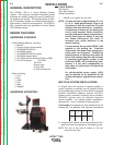
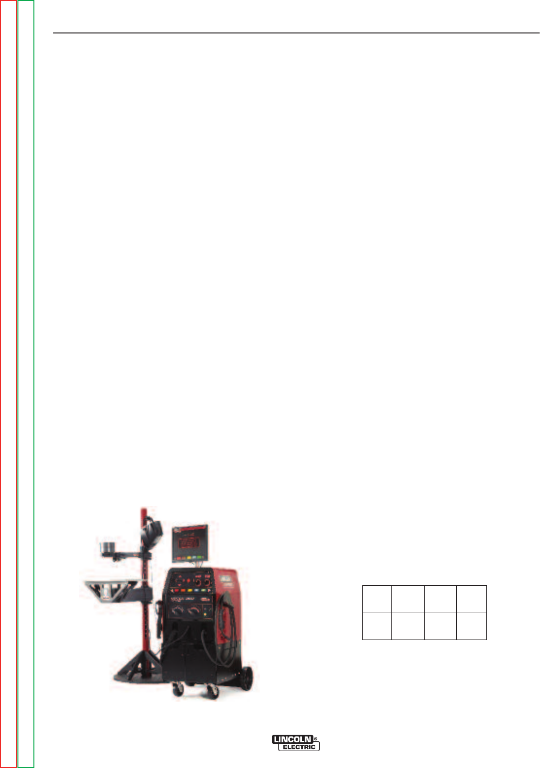
GENERAL DESCRIPTION
The VRTEX
TM
360 is a Virtual Welding Training
System. This computer controlled interactive system
simulates arc welding through the use of realistic pud-
dle graphics and sounds. This training system is capa-
ble of simulating multiple arc welding processes on a
wide variety of weld joint configurations. The VRTEX
TM
360 represents the next generation of Virtual Reality
(VR) welding training.
DESIGN FEATURES
HARDWARE OVERVIEW:
• Virtual Welding Machine, including:
o Monitor
o Coupon Drawer (back drawer)
o VR GMAW/FCAW Gun
o VR SMAW device
o VR GMAW/FCAW Gun holder
o VR SMAW device holder
o VR Helmet w/Face Mounted Display (FMD)
o Five VR Coupons - Flat Plate
Tee Joint
Groove Joint
2” Pipe XXS
6” Pipe Schedule 40
• Stand, including:
o Post
o Arm
o Table
o Pins
o Base
o Weights
HARDWARE UNCRATING:
TOOLS NEEDED
3/8” Wrench
3/16” Allen Wrench
Phillips Screwdriver
1. Decide on a location for your unit.
NOTE: The unit will take up approximately 8’ L x 8’
D x 8’ H. Keep approximately 3 feet in all
directions of both the stand and VR weld
machine free from obstruction. In addition,
be conscious of where you are placing the
unit to avoid magnetic fields, conductive,
and high frequency objects and processes.
Having these types of objects in the area
can cause interference and result in
increased jitter and/or distortion in the
motion tracking.
For best results, do not install VRTEX
TM
360
machine in the welding lab. Electrical
interference from power lines, though gen-
erally small, can be present. Therefore all
electrical power or lighting wiring within 50
feet of the welding area shall be enclosed
in grounded rigid metallic conduit. In the
event the VRTEX
TM
360 is affected by inter-
ference, it is the user's responsibility to
take steps to isolate and/or eliminate the
interference.
An uninterruptible power supply (UPS)
may be required for the protection of the
system from power irregularities or disrup-
tion.
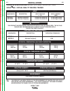
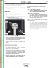
MULTIPLE SYSTEM INSTALLATIONS
If multiple units are required to operate together a
unique frequency transmitter can be installed during
the manufacturing process at Lincoln Electric to reduce
potential interference between systems. AD1332-1
systems have a standard frequency source installed.
AD1332-2 systems have an alternate frequency
source installed. For multiple system installations,
alternate the -1 and -2 systems for best operation:
For Example: If 8 systems are to be installed in the VR
welding lab, the standard and alternate frequencies
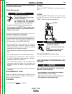
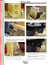
2. Using the 3/8” wrench, remove the screws from the
upper and lower front panels on the shipping crate.
NOTE: The rear of the crate is nailed on. Do not
remove at this time.
-1 -2 -1 -2
-2 -1 -2 -1
Return to Section TOC Return to Section TOC Return to Section TOC Return to Section TOC
Return to Master TOC Return to Master TOC Return to Master TOC Return to Master TOC