


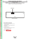

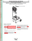
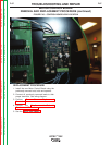


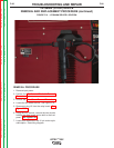
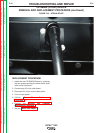


FIGURE F.40 – CONTROL BOARD LEAD LOCATION
MOTOR CONTROL BOARD
REMOVAL AND REPLACEMENT PROCEDURE (continued)
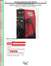
REPLACEMENT PROCEDURE
1. Install the new Motor Control Board using the
previously removed nuts, bolts and spacers.
2. Connect all previously removed leads to their
proper terminals. See wiring diagram.
3. Perform Case Cover Replacement
Procedure.
4. Perform the Monitor and Pedestal
Replacement Procedure.
5. See the Retest After Repair.
TROUBLESHOOTING AND REPAIR
F-87 F-87
VRTEX
TM
360
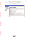
Return to Section TOC Return to Section TOC Return to Section TOC Return to Section TOC
Return to Master TOC Return to Master TOC Return to Master TOC Return to Master TOC