


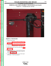


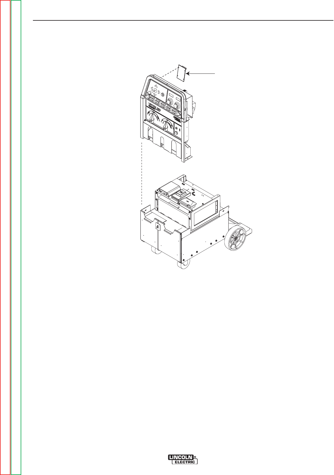
MOTOR CONTROL BOARD
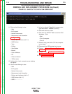
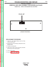
FIGURE F.39 – MOTOR CONTROL BOARD LOCATION
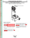
MOTOR CONTROL BOARD
REMOVAL AND REPLACEMENT PROCEDURE (continued)
REMOVAL PROCEDURE
1. Remove input power.
2. Perform the Monitor and Pedestal Removal
Procedure.
3. Perform the Case Cover Removal Procedure.
4. Locate the Motor Control Board. See Figure
F.39.
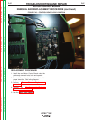
5. Label all leads and associated terminals for
reassembly.
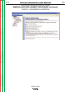
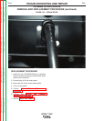
6. Using the small flathead screwdriver, remove
the 6 leads from the bottom terminal strip. See
Figure F.40. See the Wiring Diagram.
7. Using the small flathead screwdriver, remove
the three leads (50W, 20, 18) from the top ter-
minal strip on the Motor Control Board. See
Figure F.40. See Wiring Diagram.
8. Using a 5mm wrench, remove the four mount-
ing nuts, bolts and spacers from the corners of
the Motor Control Board. Note spacer positions
for reassembly.
TROUBLESHOOTING AND REPAIR
F-86 F-86
VRTEX
TM
360
Return to Section TOC Return to Section TOC Return to Section TOC Return to Section TOC
Return to Master TOC Return to Master TOC Return to Master TOC Return to Master TOC