


If for any reason you do not understand the test procedures or are unable to perform the tests/repairs safely,
contact the Lincoln Electric Service Department for technical troubleshooting assistance before you proceed.
Call 1-
888-935-3878
.
CAUTION
TROUBLESHOOTING AND REPAIR
F-8 F-8
VRTEX
TM
360
Observe Safety Guidelines detailed in the beginning of this manual.
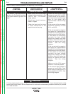
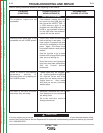
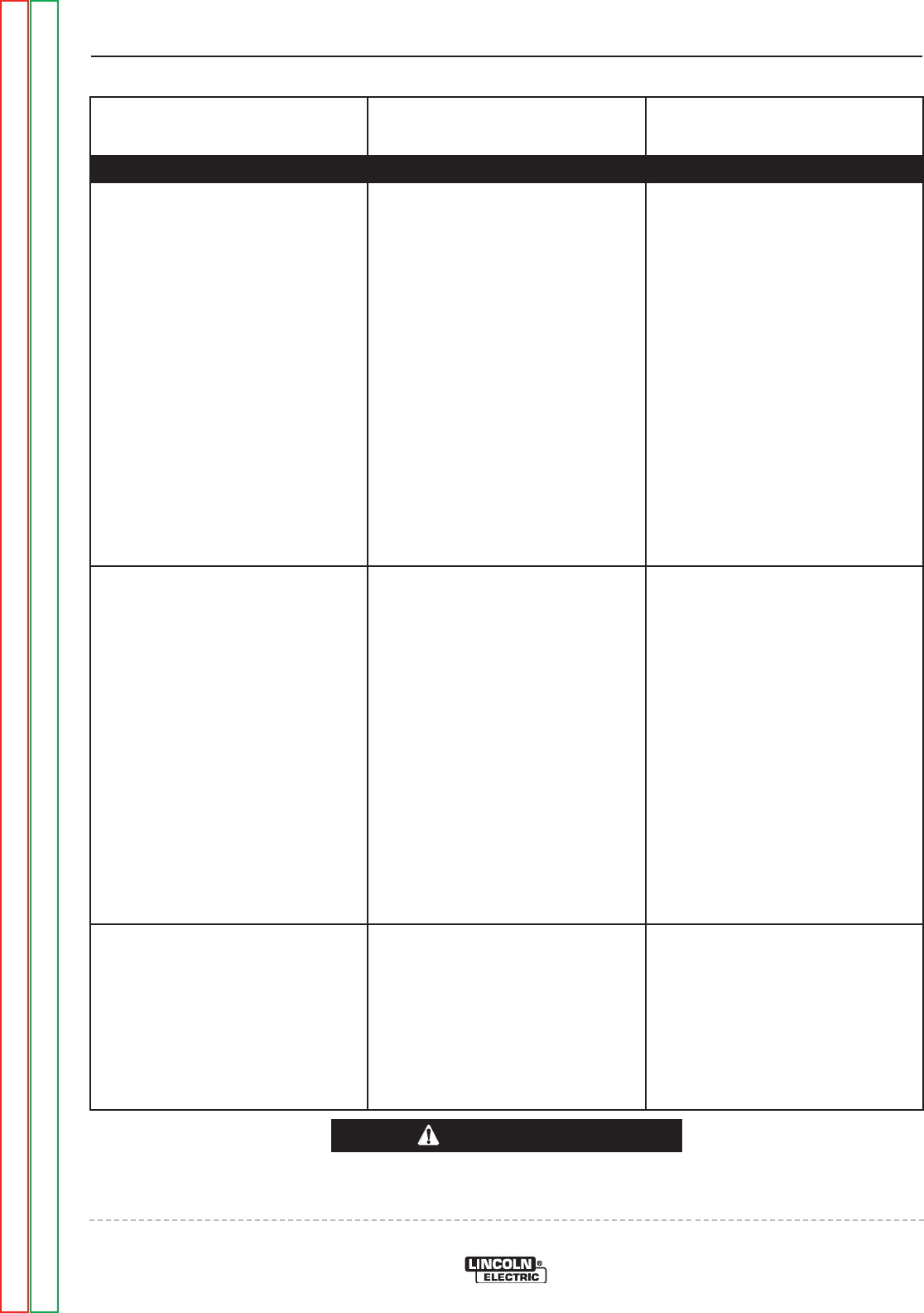
PROBLEMS
(SYMPTOMS)
POSSIBLE AREAS OF
MISADJUSTMENT(S)
RECOMMENDED
COURSE OF ACTION
FUNCTION PROBLEMS
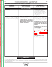
The Display P.C. Board does not
function correctly. The VRTEX
TM
360 seems to work correctly.
Check for the presence of
5VDC at the Display Board
leads #201 to #202. See the
wiring diagram. If the 5VDC is
present and the Display does
not light the Display Board may
be faulty. Replace.
If the 5VDC is not present at
the Display Board check for the
presence of 5VDC at lead
#201 to #202 at the USB
Interface Module. See the
wiring diagram. If the 5VDC is
not present the USB Interface
Module may be faulty.
Perform the USB Interface
Module Test.
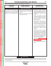
Some of the User Interface
Controls and/or Indicators do not
function.
Check the functionality of the
device(s) in question. The
switches and Joy Stick contacts
are momentary, normally open
devices. The indicators are
colored LEDs. See the wiring
diagram.
The Wire Feed Speed and
Output Controls are encoders
and are connected to the User
Interface Digital IO Module. See
the wiring diagram.
Make sure the devices in
question are not damaged and
are functional.
Check the continuity between
the non-functioning device(s)
and the User Interface Digital
IO Module. Check for loose or
faulty connections. See the
wiring diagram.
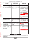
Check for loose or faulty
connections (ribbon cable)
between the User Interface
Digital I/O Module and the
terminal block interface.
Also, check the leads for loose
or faulty connections between
the terminal block interface and
the User Interface Controls and
Indicators. See wiring diagram.
All of the User Interface Controls
and Indicators do not function.
Make certain the correct input
voltage (115-230VAC single
phase) is being applied to the
VRTEX
TM
360 machine.
Perform the User Interface
Digital IO Module Test.
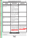
Check for loose or faulty
connections (USB cable)
between the CPU and the User
Interface Digital IO Module.
Check for loose or faulty
connections between the USB
Interface Module and the
Display Board. See the wiring
diagram.
Check for loose or faulty
connections at the USB cable
connecting the CPU to the USB
Interface Module.
Return to Section TOC Return to Section TOC Return to Section TOC Return to Section TOC
Return to Master TOC Return to Master TOC Return to Master TOC Return to Master TOC