


OPERATION
B-19 B-19
VRTEX
TM
360
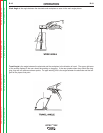
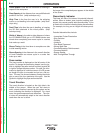
Travel Speed is how fast the electrode is traveling in
respect to the workpiece.
Dime Spacing is the distance from one solidified weld
puddle to the next. (whip technique only)
Whip Time is the time the user is in the whipping
motion, or not dwelling in the weld puddle. (whip tech-
nique only)
Dwell Time is the time the user is dwelling, or keeping
the VR Stick electrode in the virtual puddle. (whip
technique only)
Width of Weave is the side-to-side distance of where
the VR GMAW/FCAW gun or VR SMAW device was
aimed when completing one weave cycle in a series
that make up a weld.
Weave Timing is the time taken to complete one side
to side weaving motion.
Weave Spacing is the distance in the overall direction
of travel between one weave cycle in a series that
make up a weld.
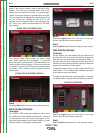
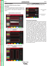
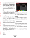
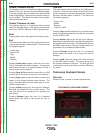
Pass number
The pass number is displayed on the left center of the
screen. To change the pass being viewed, use the joy-
stick to highlight the pass number and then joystick left
or right to change the pass number. For pipe, the infor-
mation is displayed in a similar manner on a 2D screen
as though the pipe is unraveled and put on a flat sur-
face. The user can choose between viewing the whole
pipe or one of the four quadrants of the pipe. Use the
joystick to highlight the pipe section desired.
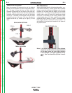
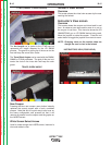
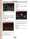
Travel Direction
The travel direction is located on the right side in the
middle of the screen. When the user first starts to
weld, a travel direction is sensed by the system and an
arrow indicating the direction is displayed. For visual
cues, the system assumes these directions. The visu-
al cues will automatically adapt to the travel direction
used when the arc is struck.
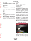
Bead Render
An image of the completed pass appears in the middle
of the screen.
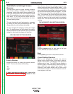
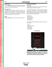
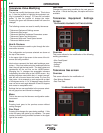
Discontinuity Indicator
The lower left side of the screen list potential disconti-
nuities. When a student uses incorrect welding tech-
niques, this causes specific weld discontinuities. A line
is drawn at the location indicating these discontinuities.
For example, too long an arc length will cause porosi-
ty.
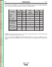
Potential discontinuities include:
• Incomplete Fusion/Penetration
• Slag Inclusion
• Porosity
• Undercut
• Poor Bead Placement
• Wrong Weld Size
• Convex/Excessive Reinforcement
• Concave/Underfill
• Excess Spatter
• Melt Through/Blow Through
Return to Section TOC Return to Section TOC Return to Section TOC Return to Section TOC
Return to Master TOC Return to Master TOC Return to Master TOC Return to Master TOC