


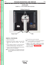


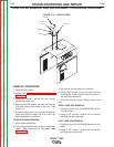
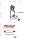
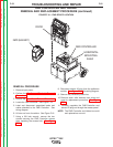

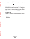

POLHEMUS MODULE
HORIZONTAL
MOUNTING
SHELF
FIGURE F.17 – POLHEMUS MODULE LOCATION
POLHEMUS MODULE REMOVAL AND REPLACEMENT
PROCEDURE (continued)
REMOVAL PROCEDURE
1. Remove input power.
2. Perform the Monitor and Pedestal Removal
Procedure.
3. Perform the Case Cover Removal Procedure.
4. Locate the Polhemus Module. See Figure F.17.
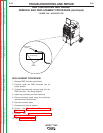
5. Label all cables and connections for reassem-
bly. See Wiring Diagram.
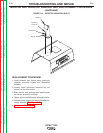
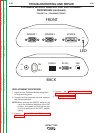
6. Remove the five associated cables connected
to the Polhemus Module. Note and label the
locations before disconnecting. See Figure
F.18.
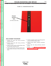
7. Carefully remove Polhemus Module from hori-
zontal mounting shelf. See Figure F.17.
NOTE: The Polhemus board is secured to the hor-
izontal mounting shelf with Hook & Loop
mounting pads.
TROUBLESHOOTING AND REPAIR
F-48 F-48
VRTEX
TM
360
Return to Section TOC Return to Section TOC Return to Section TOC Return to Section TOC
Return to Master TOC Return to Master TOC Return to Master TOC Return to Master TOC