


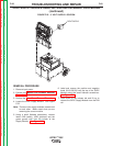

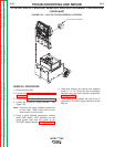
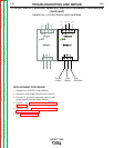
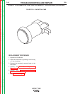

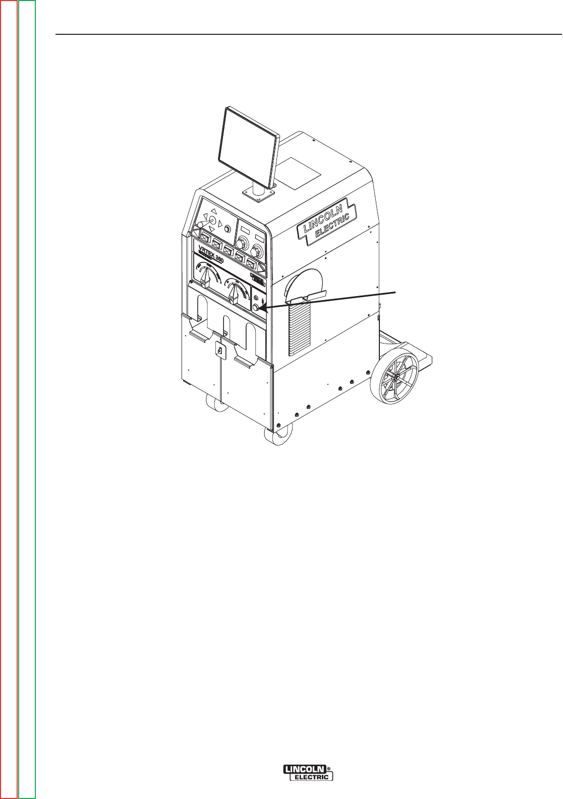
ON BUTTON
FIGURE F.27 – ON BUTTON LOCATION
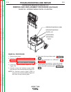
ON BUTTON REMOVAL AND REPLACEMENT PROCEDURE (continued)
REMOVAL PROCEDURE
1. Remove input power.
2. Perform the Monitor and Pedestal Removal
Procedure.
3. Perform the Case Cover Removal Procedure.
4. Locate the ON Button. See Figure F.27.
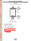
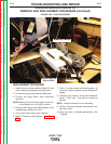
5. Label and remove the four associated leads
(101B, 103A, 90, 91) from the ON Button. See
wiring diagram.
6. Remove switch from push button by pushing in
and turning a ¼ turn counter clockwise.
7. If necessary, remove the nut and push button
assembly from front panel.
TROUBLESHOOTING AND REPAIR
F-68 F-68
VRTEX
TM
360
Return to Section TOC Return to Section TOC Return to Section TOC Return to Section TOC
Return to Master TOC Return to Master TOC Return to Master TOC Return to Master TOC