


OPERATION
B-26 B-26
VRTEX
TM
360
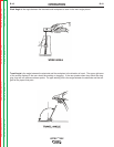
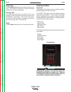
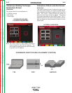
Tolerances Pattern and Aim Screen
Overview
This screen allows the user to change the type of pat-
tern being used (stringer, box weave, straight weave,
whip, triangle weave) and the position of the root of the
weld. The X and Y values change the location of
where the weld bead should be placed. This affects
the position parameter on the LASER screen. The +/-
determines how far off from the ideal position the stu-
dent can place the electrode before it results in a mis-
placed weld.
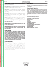
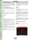
Tolerances Welding Technique
Parameters Screen
Overview
This screen allow for the modification of:
• CTWD/Arc Length
• Work Angle
• Travel Angle
TOLERANCES WELDING
TECHNIQUE PARAMETERS
PATTERN & AIM SCREEN
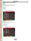
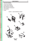
Z
Y
X
XX
X
Z
TEE PIPE GROOVE
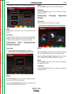
Note: The travel angle for drag welding techniques
should always be less than 90 degrees. The
travel angle for pushing technique should always
be greater than 90 degrees.
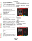
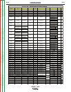
COORDINATE CHART FOR WELD PLACEMENT (POSITION)
Return to Section TOC Return to Section TOC Return to Section TOC Return to Section TOC
Return to Master TOC Return to Master TOC Return to Master TOC Return to Master TOC