


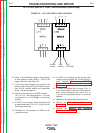


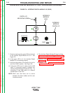

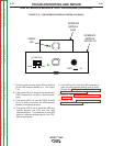
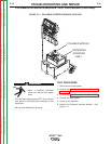
I/O LINE PULL
HIGH
LOW
- +
12VDC , 1A
INTERFACE
MODULE
DIGITAL I/O
INTERFACE
MODULE
(USB)
DIGITAL I/O
MOUNTING SCREW
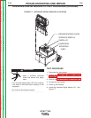
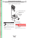
FIGURE F.8 – INTERFACE DIGITAL MODULE I/O (REAR)
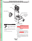
INTERFACE DIGITAL MODULE I/O TEST PROCEDURE (continued)
7. Check to make sure the green LED on the back
of the Interface Digital Module I/O is lit. See
Figure F.8.
8. If the green LED is lit, the Interface Digital
Module I/O is functioning properly.
9. Verify that the switch on the back of the unit is
set to the “HIGH” position. See Figure F.8.
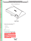
10. If the green LED is not lit, make sure the USB
cable is connected properly between the
Interface Digital Module I/O and the CPU. Try
connecting a new USB cable to a different
available port on the CPU.
NOTE: Make sure that there are no shorts
between the ribbon cables and the user
interface controls.
11. The Interface Digital Module I/O may be faulty.
Perform the Interface Digital Module I/O
Removal and Replacement Procedure.
12. Perform the Case Cover Replacement
Procedure.
13. Perform the Monitor and Pedestal
Replacement Procedure.
TROUBLESHOOTING AND REPAIR
F-29 F-29
VRTEX
TM
360
Return to Section TOC Return to Section TOC Return to Section TOC Return to Section TOC
Return to Master TOC Return to Master TOC Return to Master TOC Return to Master TOC