


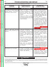


5 VOLT SUPPLY
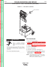
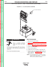
FIGURE F.1 – 5 VDC SUPPLY LOCATION
5 VDC SUPPLY TEST PROCEDURE (continued)
TROUBLESHOOTING AND REPAIR
F-16 F-16
VRTEX
TM
360
TEST PROCEDURE
1. Disconnect the input power.
2. Perform the Monitor and Pedestal Removal
Procedure.
3. Perform the Case Cover Removal Procedure.
4. Connect the input power.
5. Power up the machine.
6. Locate the 5 Volt Supply. See Figure F.1.
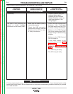
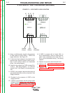
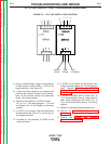
7. Check to make sure the green LED on back of
power supply is lit. See Figure F.2. If so, con-
tinue to step 10.
NOTE: This indicates that the machine is receiv-
ing the correct input power. If the green
LED is not lit, continue to step 8.
ELECTRIC SHOCK can kill.
• Have a qualified individual
install and service this equip-
ment.
• Turn the input supply power OFF at the discon-
nect switch or fuse box before working on this
equipment.
• Do not touch electrically hot parts.
------------------------------------------------------------------
WARNING
Return to Section TOC Return to Section TOC Return to Section TOC Return to Section TOC
Return to Master TOC Return to Master TOC Return to Master TOC Return to Master TOC