


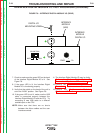


I/O LINE PULL
HIGH
LOW
- +
12VDC , 1A
INTERFACE
MODULE
DIGITAL I/O
INTERFACE
MODULE
(USB)
GREEN
LED
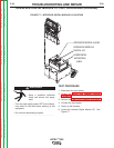
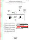
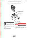
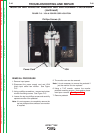
FIGURE F.10 – USB INTERFACE MODULE GREEN LED (REAR)
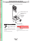
USB INTERFACE MODULE TEST PROCEDURE (continued)
7. Check to make sure the green LED on the back
of the USB Interface Module is lit. See Figure
F.10.
8. If the green LED is lit, check for the presence of
5VDC at leads 201(-) to 202(+). See wiring dia-
gram.
9. If the green LED is lit and the 5VDC at leads
201(-) to 202(+) is present, the USB Interface
Module is functioning properly.
10. If the green LED is not lit, check the USB con-
nection between the CPU and the USB
Interface Module. Try connecting a new USB
cable to a different available port on the CPU.
See wiring diagram.
11. If the LED is not lit and the USB connection is
good, the USB Interface Module may be faulty.
Perform the USB Interface Module Removal
and Replacement Procedure.
12. Perform the Case Cover Replacement
Procedure.
13. Perform the Monitor and Pedestal
Replacement Procedure.
TROUBLESHOOTING AND REPAIR
F-33 F-33
VRTEX
TM
360
Return to Section TOC Return to Section TOC Return to Section TOC Return to Section TOC
Return to Master TOC Return to Master TOC Return to Master TOC Return to Master TOC