


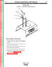


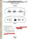
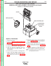

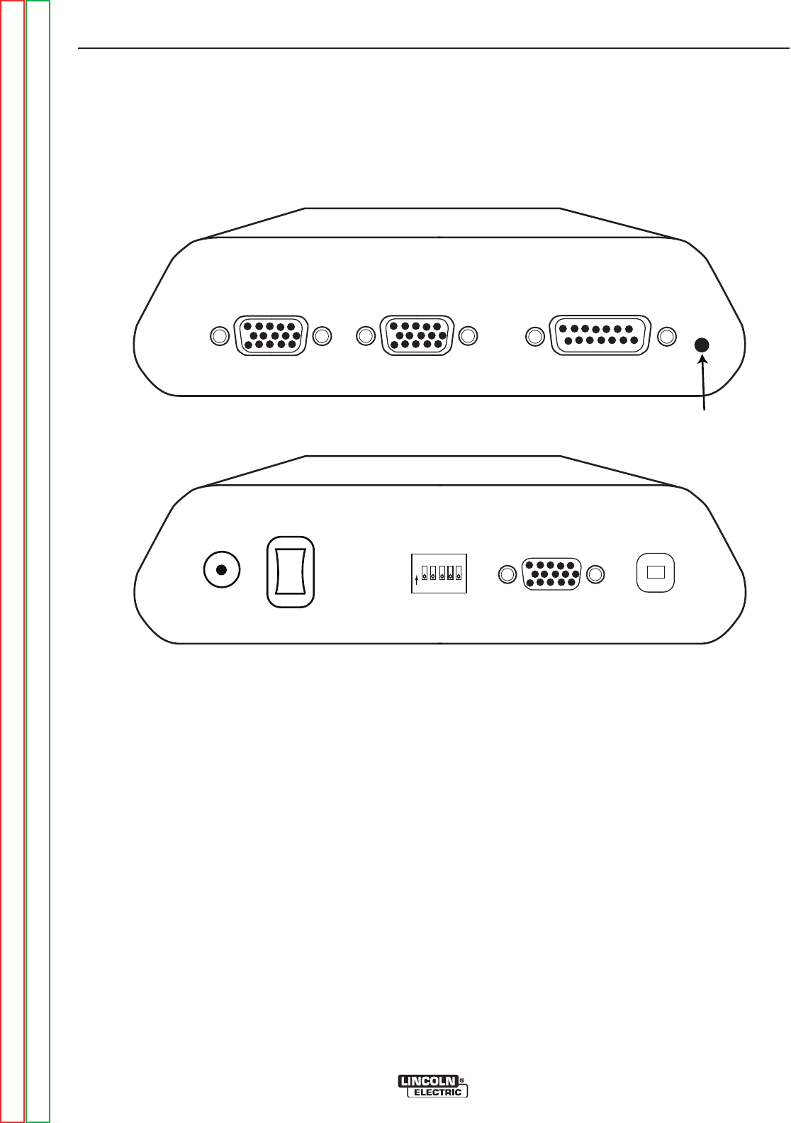
SENSOR 1
SENSOR 2
SOURCE
S
YS
RS 232 USB
CONFIG
O
N
ON
OFF
DC
IN
FRONT
BACK
LED
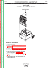
FIGURE F.18 – POLHEMUS (FRONT)
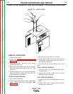
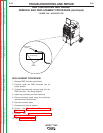
POLHEMUS MODULE REMOVAL AND REPLACEMENT
PROCEDURE (continued)
REPLACEMENT PROCEDURE
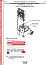
1. Install the new Polhemus Module using Hook
& Loop mounting pads.
2. Connect the five previously removed cables to
the Polhemus Module.
NOTE: Make sure that the ON/OFF switch at the
rear of the Polhemus Module is in the “ON”
position. Also make sure that the five pins
on the dip switch are in the “OFF” position
(down).
3. Perform Case Cover Replacement
Procedure.
4. Perform the Monitor and Pedestal
Replacement Procedure.
5. See Retest After Repair.
TROUBLESHOOTING AND REPAIR
F-49 F-49
VRTEX
TM
360
Return to Section TOC Return to Section TOC Return to Section TOC Return to Section TOC
Return to Master TOC Return to Master TOC Return to Master TOC Return to Master TOC