


THEORY OF OPERATION
E-3 E-3
VRTEX
TM
360
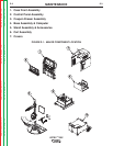
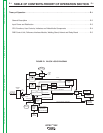
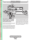
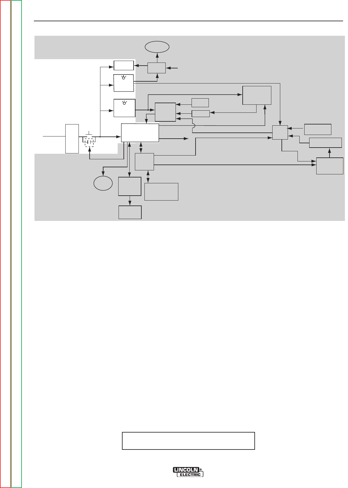
FIGURE E.3 - INPUT POWER & DISTRIBUTION
INPUT POWER & DISTRIBUTION
The single phase input power (115-240VAC) is applied
through a terminal strip and a momentary switch to four
discreet components. They are the computer assembly
(CPU), the 5VDC supply, the 12VDC supply and the
monitor. These components rectify the AC input and
regulate the resultant DC voltage to operate the inter-
nal electronics of the VRTEX
TM
360.
When the CPU has been energized the momentary
“ON” switch is bypassed by the interlock relay. The
5VDC created by the CPU is applied, via a USB cable
to the interlock relay. The independent 5VDC supply
provides power to the Polhemus Interface Module, and
the FMD Control Unit. The other independent 12VDC
supply provides power to the VGA Splitter and via the
Relay PC Board to the Motor Control Board.
115/240 VAC
50/60 HERTZ
SINGLE PHASE
INPUT
TERMINAL
STRIP
ON
SWITCH
INTERLOCK
RELAY
5 VDC USB
SIGNAL
AUDIO 1
AUDIO
R
ECEPTACLE
DISPLAY
LED
PC BOARD
INTERFACE
MODULE
DIGITAL
(
USB)
VIDEO
R
ECEPTACLE
MONITOR VGA
SPLITTER
12 VDC
GREEN LED
12 VDC
SUPPLY
GREEN LED
5 VDC
SUPPLY
5 VDC
C
PU
COMPUTER ASSEMBLY
U
S
B
S
I
G
N
A
L
U
S
B
POLHEMUS
INTERFACE
MODULE
FROM
CPU
VGA 1
INTERFACE
MODULE
DIGITAL
I/O
U
S
B
PROCEDURE SELECTIONS
TO VGA SPLITTER
USER INTERFACE
CONTROLS AND
INDICATORS
(MULTIPLE DEVICES)
WELDING
STAND
HELMET
RELAY
PC
BOARD
<
12 VDC
5 VDC
V
ISUAL AND AUDIO SIGNALS
FMD
CONTROL
UNIT
MOTOR CONTROL COMMANDS
12 VDC
M
IG GUN
DEVICE
STICK ELECTRODE
DEVICE
MOTOR
CONTROL
PC BOARD
MOTOR
SIGNALS
V
G
A
3
+
4
A
N
D
A
U
D
I
O
2
12 VDC
VRTEX 360 THEORY OF OPERATION
NOTE: Unshaded areas of Block Logic
Diagram are the subject of discussion
Return to Section TOC Return to Section TOC Return to Section TOC Return to Section TOC
Return to Master TOC Return to Master TOC Return to Master TOC Return to Master TOC