


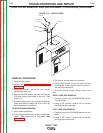
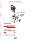
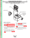

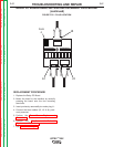


FMD CONTROLLER
HORIZONTAL
MOUNTING
SHELF
FMD (HELMET)
DOOR
FIGURE F.19 – FMD DEVICE LOCATION
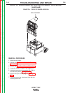
FMD CONTROLLER AND HELMET
REMOVAL AND REPLACEMENT PROCEDURE (continued)
REMOVAL PROCEDURE
1. Remove input power.
2. Perform the Monitor and Pedestal Removal
Procedure.
3. Perform the Case Cover Removal Procedure.
4. Locate the FMD Controller. See Figure F.19.
5. Label and disconnect associated leads and
cables attached to the FMD Controller. See
wiring diagram.
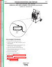
6. Lift door on front of machine. See Figure F.19.
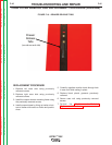
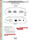
7. Using a 3/8 inch wrench, remove the two
screws securing the FMD Controller access
plate exposing the access hole. See Figure
F.20.
8. Disconnect sensor #2 plug from the polhemus
module. See Figure F.18. See wiring diagram.
9. Remove any necessary cable ties.
10. Remove strain relief devices from wires and
save for replacement procedure. See Figure
F.20.
11. Carefully negotiate the FMD Controller and
sensor #2 plug out through the access panel.
NOTE: The FMD Controller and Helmet are sold
and replaced as one unit.
TROUBLESHOOTING AND REPAIR
F-52 F-52
VRTEX
TM
360
Return to Section TOC Return to Section TOC Return to Section TOC Return to Section TOC
Return to Master TOC Return to Master TOC Return to Master TOC Return to Master TOC