


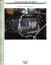
CPU
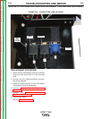
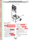
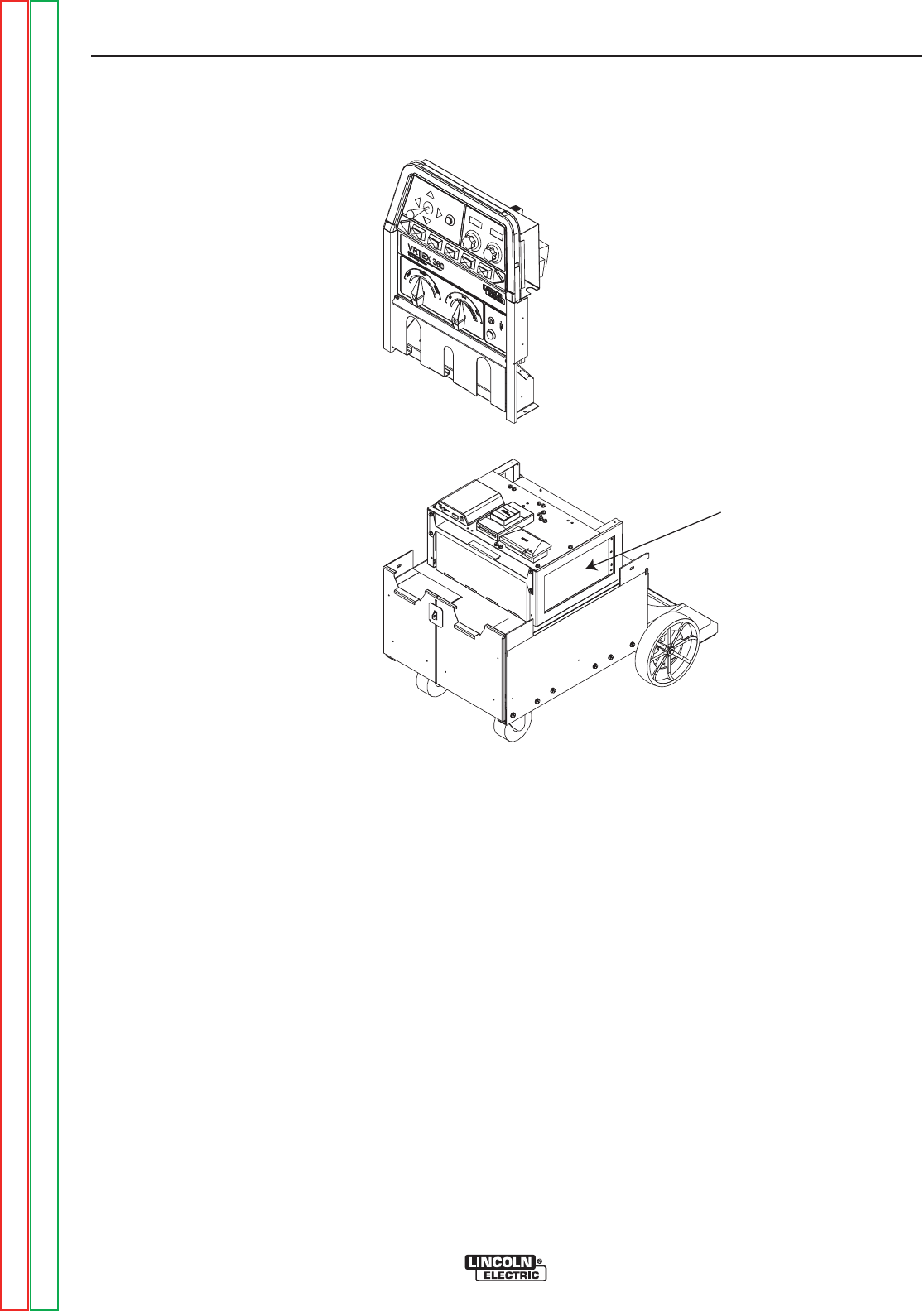
FIGURE F.49 – CPU LOCATION
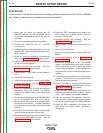
CPU REMOVAL AND REPLACEMENT PROCEDURE (continued)
REMOVAL PROCEDURE
1. Remove input power.
2. Perform the Monitor and Pedestal Removal
Procedure.
3. Perform the Case Cover Removal Procedure.
4. Locate the CPU. See Figure F.49.
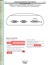
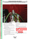
5. Using a 3/8” wrench, remove the first three
ground leads and associated washers from the
inside of the case back. See Figure F.50.
NOTE: Leave fourth ground lead connected. Case
back can be removed with the fourth
ground lead still connected.
6. Remove the strain relief from the cable leading
to the welding stand. See Figure F.50.
7. Using the 3/8” wrench, remove the three bottom
screws from the case back. See Figure F.51.
8. Carefully slide the case back to the side while
being careful not to stretch or break any leads
or connections.
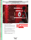
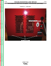
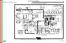
9. Label and remove the five USB cables from the
rear of the CPU. See Figure F.52. See wiring
diagram.
10. Label and remove the three VGA cables from
the rear of the CPU. See Figure F.52. See
wiring diagram.
11. Label and remove the audio cable. See Figure
F.52. See wiring diagram.
12. Using a 3/8” wrench, remove the four screws
from the horizontal mounting shelf.
13. Lift the shelf high enough to “Break” the bond
between the foam and the CPU.
14. Carefully slide the CPU toward the back of the
machine.
NOTE: There are Hook & Loop connections
between the CPU and the top and bottom
foam layers.
15. Remove the CPU.
TROUBLESHOOTING AND REPAIR
F-106 F-106
VRTEX
TM
360
Return to Section TOC Return to Section TOC Return to Section TOC Return to Section TOC
Return to Master TOC Return to Master TOC Return to Master TOC Return to Master TOC