


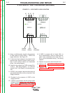

+ + - -
5VDC/5A
DPP25-5
N L
D
C ON
DPP50-15DPP50-15
+ + - - + + - -
15VDC/3.4A15VDC/3.4A
N LN L
DC ONDC ON
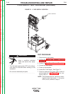
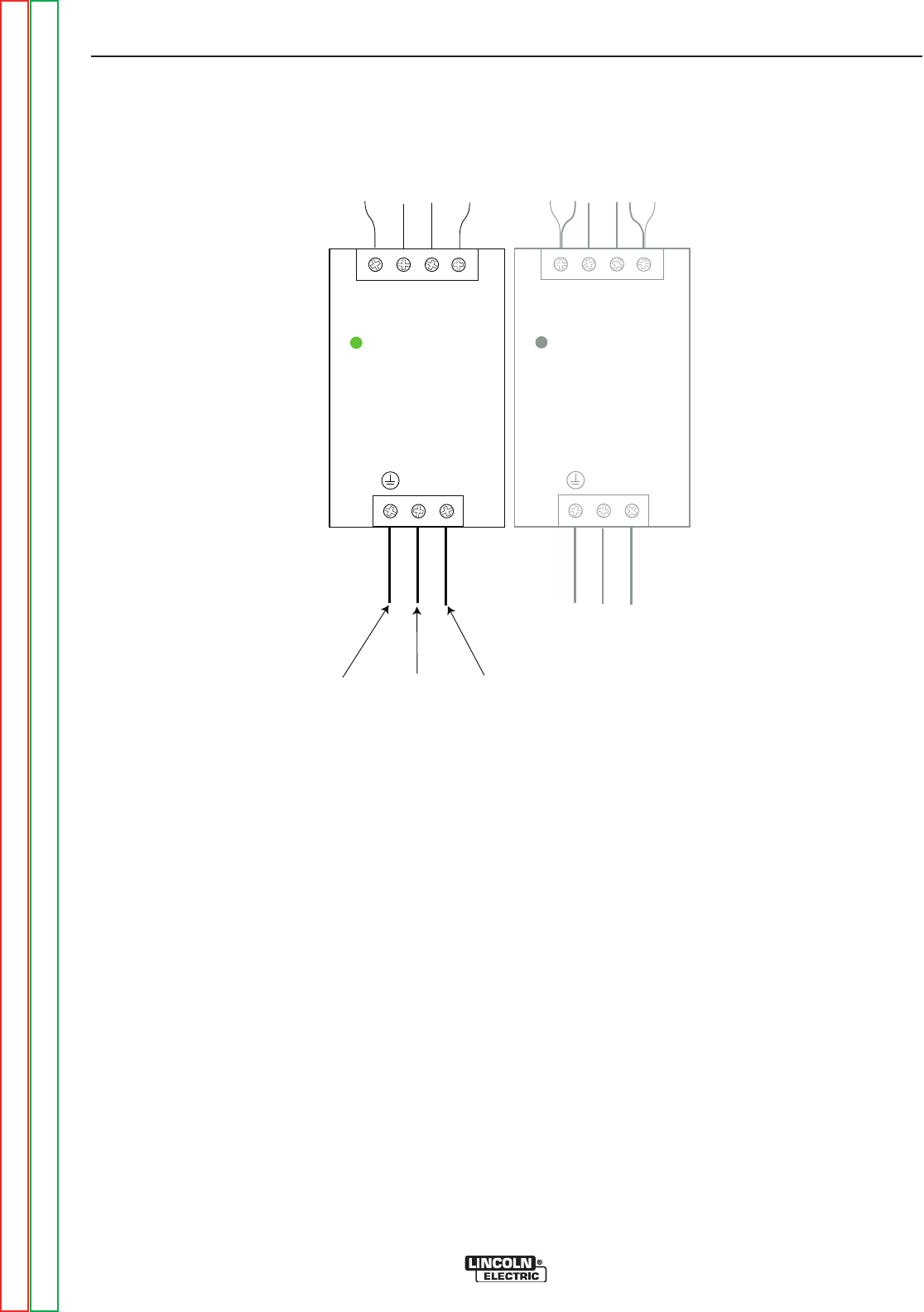
Ground
(Green)
102A
(White)
103B
(Pink/Red)
81 81 50 50
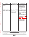
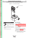
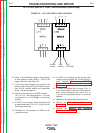
FIGURE F.2 – 5 VDC SUPPLY LEAD LOCATION
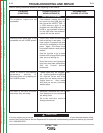
5 VDC SUPPLY TEST PROCEDURE (continued)
8. Using a volt/ohmmeter, check for the presence
of input power at leads 102A to 103B at the
supply terminals. See Figure F.2.
9. If the correct input voltage is not present in the
previous step, check for loose or faulty connec-
tions at the terminal blocks and associated
wiring. See wiring diagram.
10. Check for the presence of 5VDC at leads 50(-)
to 81(+). See wiring diagram. If 5 volts are
present, the 5 Volt Supply is functioning prop-
erly.
11. If 5VDC is not present, label and disconnect all
associated leads (50(-) to 81(+)) from the 5 Volt
Supply terminals.
12. Re-check for the presence of 5VDC at the
supply terminals.
13. If 5VDC is not present and the correct input
voltage is being applied, the 5 Volt Supply is
faulty. Replace. Perform the 5 VDC Supply
Removal and Replacement Procedure.
14. If 5VDC is present with all leads (50(-) to
81(+)) disconnected, there is a heavy load or
short circuit associated with leads 50(-) to
81(+) and the associated wiring. See wiring
diagram.
15. Replace all previously disconnected leads.
16. Perform the Case Cover Replacement
Procedure.
17. Perform the Monitor and Pedestal
Replacement Procedure.
TROUBLESHOOTING AND REPAIR
F-17 F-17
VRTEX
TM
360
Return to Section TOC Return to Section TOC Return to Section TOC Return to Section TOC
Return to Master TOC Return to Master TOC Return to Master TOC Return to Master TOC