


DR4300 Circular Chart Recorder
DR4300 Circular Chart Recorder Product Manual 12/03
x
Table 4-33 Procedure for Resetting Totalizer ..........................................................................................................137
Table 4-34 Procedure for Starting Timer .................................................................................................................138
Table 4-35 Procedure for Resetting Limit Controller...............................................................................................139
Table 5-1 Voltage and Resistance Equivalents for 0 % and 100 % Range Values ..................................................143
Table 5-2 Equipment Needed for Calibration ..........................................................................................................144
Table 5-3 Disconnect the Field Wiring ....................................................................................................................145
Table 5-4 General Calibration Set Up Procedure.....................................................................................................146
Table 5-5 Set Up Wiring Procedure for Thermocouple Inputs Using a Compensated Calibrator ..........................147
Table 5-6 Set Up Wiring Procedure for Thermocouple Inputs Using an Ice Bath...................................................148
Table 5-7 Set Up Wiring Procedure for Calibrating RTD Inputs.............................................................................149
Table 5-8 Set Up Wiring Procedure for Calibrating Millivolts, Volts, and Milliamps Inputs .................................150
Table 5-9 Input Calibration Procedure Sequence.....................................................................................................151
Table 5-10 Set Up Wiring Procedure for Current Proportional Output ...................................................................153
Table 5-11 Procedure for Calibrating Current Output..............................................................................................154
Table 6-1 Procedure for Replacing the Chart...........................................................................................................158
Table 6-2 Procedure for Replacing the Ink Cartridge ..............................................................................................159
Table 6-3 Maximizing Pen Life................................................................................................................................160
Table 7-1 Observable Symptoms of Failure.............................................................................................................163
Table 7-2 Troubleshooting Recorder Failure Symptoms .........................................................................................165
Table 7-3 Troubleshooting Pen Trace Failure Symptoms........................................................................................166
Table 7-4 Troubleshooting Chart Rotation Failure Symptoms ................................................................................167
Table 7-5 Troubleshooting Erratic Pen Movement Symptoms ................................................................................168
Table 7-6 Procedure for Pen Alignment...................................................................................................................169
Table 8-1 Procedure for Identifying the Software Version ......................................................................................173
Table 8-2 Power-Up Diagnostic Tests......................................................................................................................174
Table 8-3 Procedure for Displaying the Results of Self-Diagnostics.......................................................................175
Table 8-4 Error Messages.........................................................................................................................................177
Table 8-5 Observable Symptoms of Failure.............................................................................................................179
Table 8-6 Troubleshooting Recorder Failure Symptoms .........................................................................................181
Table 8-7 Troubleshooting Pen Trace Failure Symptoms........................................................................................182
Table 8-8 Troubleshooting Chart Rotation Failure Symptoms ................................................................................183
Table 8-9 Troubleshooting Erratic Pen Movement Symptoms ................................................................................184
Table 8-10 Troubleshooting Keypad and/or Display Failure Symptoms .................................................................184
Table 8-11 Troubleshooting Relay Output Failure Symptoms.................................................................................185
Table 8-12 Troubleshooting External Alarm Function Failure Symptoms ..............................................................186
Table 8-13 Troubleshooting Remote Switch (Digital Input) Function Failure Symptoms ......................................186
Table 8-14 Troubleshooting Modbus Communications ...........................................................................................187
Table 8-15 Procedure for Aligning Pen at Zero and Span .......................................................................................188
Table 9-1 Door Assembly Parts................................................................................................................................192
Table 9-2 Chart Plate Assembly Parts......................................................................................................................193
Table 9-3 Basic Recorder Parts ................................................................................................................................195
Table A-1 Typical Reference Accuracy ...................................................................................................................200
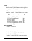
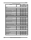
Table B-1 10-inch Single Range Chart Part Numbers..............................................................................................203
Table B-2 10-inch Dual Range Chart Part Numbers................................................................................................208
Table C-1 Prompt Hierarchy and Available Selections............................................................................................218
Table C-2 Run/Monitor Functions ...........................................................................................................................221
Table D-1 Procedure for Starting Accutune II .........................................................................................................226
Table D-2 Procedure for Using Accutune for Duplex Control ................................................................................227