


Installation
12/03 DR4300 Circular Chart Recorder Product Manual
35
2.5.4 Communication (Optional)
Introduction
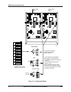
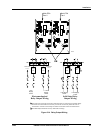
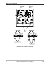
If the recorder hardware supports optional Modbus RTU communication, the communication link is wired
to the terminal block on the communication board in the upper left corner of the case.
ATTENTION
Network address, baud rate, and transmitter delay are configurable for models with a display (see
Section 4).
For models without a display the address of pen 1 is fixed at 127, baud rate is fixed at 9600, and
there is no transmitter delay. Only one pen channel with the fixed address of 127 can be on the
network. Pen channel 2, if present in the recorder, cannot communicate. (Display is required to
configure a unique address for the second pen to communicate.)
Procedure
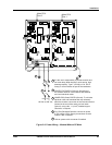
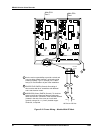
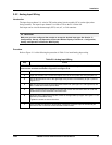
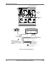
Refer to Figure 2-13 while following the procedure in Table 2-11 to install communication wiring.
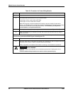
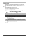
Table 2-11 Communication Wiring
Step Action
ATTENTION To avoid damaging the recorder, be sure that you install the power wires into the
correct screw terminals as shown Figure 2-9 and Figure 2-10.
1
Open the recorder door. Loosen the captive screw in the chart plate and swing the plate out.
2
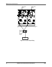
Locate the terminal block on the optional communication printed circuit assembly in the upper
left corner of the case. (See Figure 2-13.)
3
Run the communication wires through the appropriate conduit hole (see Figure 2-7 and Figure
2-8). DO NOT bundle them with the power wires.
4
Strip 1/4-inch maximum of insulation from the end of each wire and form end to fit under a
screw connection.
5
Insert the wires under the appropriate screws (labeled on assembly). Tighten the screws to
secure the wires.