


DR4300 Circular Chart Recorder
166 DR4300 Circular Chart Recorder Product Manual 12/03
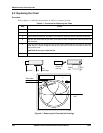
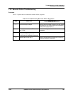
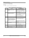
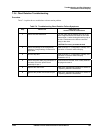
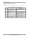
7.3.3 Pen Trace Troubleshooting
Procedure
Table 7-3 explains how to troubleshoot a pen trace problem.
Table 7-3 Troubleshooting Pen Trace Failure Symptoms
Step What to do How to do it or
where to find the instructions
1
Check the ink cartridge for proper
installation.
Reposition or replace the ink cartridge as
described in Section 6 – Routine Maintenance.
If the pen arm is severely warped, replace the
pen arm as described in Section 9 – Replacing
Hardware Assemblies.
2
Check that the chart agrees with the
actuation type and chart set up.
Replace wrong chart with correct chart. Refer to
Section 3 – Configuration, Startup, and Operation
of Recorder without Display for instructions for
viewing the configuration.
See Section 6 – Routine Maintenance for
instructions for replacing the chart.
3
Check the pen alignment. Follow the procedure in Subsection 7.4.
4
Look at printed circuit assembly (PCA) for
the pen to see if the red* LED is lit. This
LED is lit when the PCA failed a self-
diagnostic, or an out-of-range input has
been detected. (Flashing green LED is
OK, it indicates that the processor is
active.)
Press the reset switch SW2. The PCA will be
initialized. If the problem was a software error,
the error may be cleared by the reset.
*For Recorders with a display, the red LED is
used by an internal control signal and is not a
fault indicator.
5
Check the sensor for the proper type and
its ability to function.
Verify the input configuration data and operation
of the sensor.
Measure input signal at TB2 or apply calibration
source to verify input signal.
6
Replace the servo plate assembly. Refer to the replacement procedure in Section 9
– Replacing Hardware Assemblies.
7
Replace the printed circuit assembly for
the pen with the problem.
Refer to the replacement procedure in Section 9
– Replacing Hardware Assemblies.