


DR4300 Circular Chart Recorder
DR4300 Circular Chart Recorder Product Manual 12/03
26
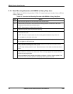
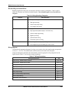
Wire bundling recommendations
Bundling together the wrong wires can adversely affect the recorder’s performance. Table 2-6 shows
which wire functions may usually be bundled together. Do not bundle together wires from different
categories.
Table 2-6 Wiring Bundling Categories
Category Wire Functions
1
• Line power wiring
• Earth ground wiring
• Control relay output wiring
• Line voltage alarm wiring
2 Analog signal wire, such as:
• Input signal wire (thermocouple, 4 to 20 mA, etc.)
• 4-20 mA output signal wiring
• Digital input wiring
• Communication wiring
• Transmitter power out wiring
3
• Low voltage alarm relay output wiring
• Low voltage wiring to solid state type control circuits
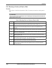
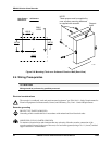
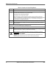
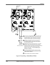
Wiring diagrams
To determine the appropriate diagrams for wiring your recorder, refer to the model number interpretation
in Section 1 - Overview. The model number of the recorder can be found on the chart plate.
Using the information contained in the model number, select the appropriate wiring diagrams from the
figures listed in Table 2-7 and wire the recorder accordingly.
Table 2-7 Wiring Illustrations
Wiring Requirements See
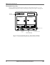
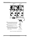
Power Wiring - Models Without CE Mark Figure 2-9
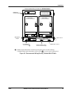
Power Wiring - Models With CE Mark Figure 2-10
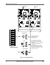
Analog Input Wiring Figure 2-11
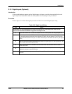
Digital Input Wiring Figure 2-12
Communication Wiring Figure 2-13
Relay Output Wiring Figure 2-14
Open Collector Relay Output Wiring Figure 2-15
Current Output Wiring Figure 2-16
Transmitter Power Out Wiring Figure 2-17