


Input and Output Calibration for Recorder with Display
12/03 DR4300 Circular Chart Recorder Product Manual 151
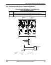
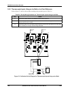
5.5 Input Calibration Procedure
Introduction
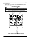
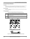
Before performing this procedure, be sure the recorder is wired for calibration as described in Subsection
5.4. Apply power and allow the recorder to warm up for 30 minutes before you calibrate.
Make sure “LOCK” is set to “NONE” (see Section 4 - Configuration, Startup and Operation of Recorder
with Display).
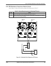
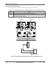
ATTENTION
For Milliamp inputs, be sure the current source is at zero before switching on the calibrator.
Do not switch the calibrator on/off while it is connected to the recorder’s input. Failure to observe
this precaution could result in damage to input circuits.
Calibration procedure sequence
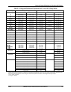
The calibration procedure sequence for all inputs is listed in Table 5-9. The calibration procedure for inputs
1 and 2 is identical. The displays indicate the input number.
Press the
FUNC key to change display as required (INP1 or INP2).
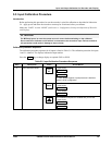
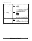
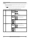
Table 5-9 Input Calibration Procedure Sequence
Step Description Press Action/Result
1
Enter Calibration Mode
SET
UP
until you see
CAL
U
pp
er Dis
p
la
y
INPUT
Lower Dis
p
la
y
If “CAL” doesn’t appear or prompt access is declined,
check “LOCK” configuration.
FUNC
You will see:
DIS
U
pp
er Dis
p
la
y
CAL IN
Lower Dis
p
la
y
The calibration sequence is enabled and you will see:
BEGIN
U
pp
er Dis
p
la
y
CAL IN
Lower Dis
p
la
y