


DR4300 Circular Chart Recorder
82 DR4300 Circular Chart Recorder Product Manual 12/03
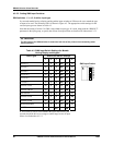
If the switch and the set up parameter do not match, operator confusion may result. For example, in case of
mismatch the displayed value could first go under range, then quickly go over range. However, except for
the brief period before the software reacts to the out-of-range value, the effect of the mismatch is
insignificant.
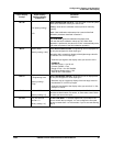
1
2
3
4
5
6
ON
7
8
P1 P2 P3
1
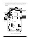
Relay Output
Keyboard/Display
Connector
SW1
Configuration
Switches
TB2
AC Power
123456
ON
SW6
Input Switches
Pen #2 Connector
Pen #1 Connector
Chart Motor
SW2
SW3
SW4
Input Connector
TB1
LN
LOWER RAISE
S2 = Reset
S3 = Lower
S4 = Raise
J4
J3
SETUP
RUN
SW5
Run/Setup
Switch*
J1
24084
TB5
21
TB3
3
Current Output/Aux. Output
21
TB4
3
Battery
Connector
Communications
Board Connector
*Also used as a
lockout switch
in the “SETUP”
position.
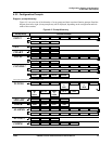
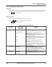
Figure 4-3 Location of Switches and Relays