


Installation
12/03 DR4300 Circular Chart Recorder Product Manual
25
TB1
TB2
P3D
TB5
TB4
TB3
TB1
TB2
P3D
TB5
TB4
TB3
Pen 2 Main
Printed Circuit Board
Pen 1 Main
Printed Circuit Board
J3
Communications
Printed Circuit Board
24 V Power Supply
RS485/422
Communications
Inputs 1 and 2
A C
Filter
Assembly
A.C. Mains and
Ground Wire
Current Outputs 1 and 2
and 24 V Power Supply
Digital Inputs 1 and 2
Relay/Alarm
Outputs
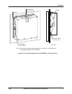
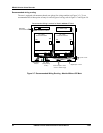
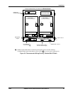
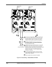
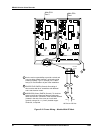
Recommended Wiring Locations for CE Mark Models
1
1
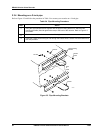
A braided copper shield shall be connected to ground (green screw on the filter assembly).
A separate braided copper shield shall be used to connect
on rear of case to chassis ground
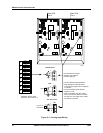
Digital Input Board Digital Input Board
24819
Figure 2-8 Recommended Wiring Routing - Models With CE Mark