


DR4300 Circular Chart Recorder
128 DR4300 Circular Chart Recorder Product Manual 12/03
4.5 Operation of Recorder with Display and Keypad
4.5.1 Monitoring Your Recorder
4.5.1.1 Overview
Introduction
In addition to the historical chart record, you can monitor the recorder’s indicators and displays to see real
time values of inputs. If control is enabled, then setpoint, output, and deviation values can also be
displayed.
Set up values can also be viewed. Depending on the lockout status, configuration values may also be
changed.
As a background task the recorder runs self-diagnostics on the printed circuit assemblies for the pens as
described in Section 8 – Troubleshooting and Pen Alignment of Recorder with Display. If a test is failed,
an error message will be displayed as described in Subsection 4.5.1.4. Depending on the recorder’s
configuration, a “failsafe” output value may be used for control in case of malfunction, as described in
Section 8.
4.5.1.2 Operator interface
Display
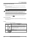
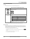
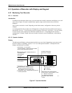
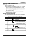
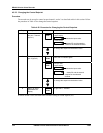
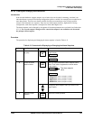
The indicators and displays on the operator interface let you see what is happening to your process and
how the recorder is responding. Figure 4-7 is a view of the operator interface. A description of the
displays and indicators is included.
24278
INP
OUT
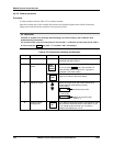
Lower Display - six characters
Normal operation - Displays selected
operating parameter label and value.
With totalization, shows totalizer value.
Configuration mode - Displays Set Up group and
function parameters.
Output relay 1 or 2
is ON, when lit.
Data displayed
is for input
Channel 1 or 2
Upper Display - four characters
Normal operation - Displays process variable
(PV) for the selected input channel.
Configuration mode - Displays selection or
parameter value.
Indicates controller mode:
M = Manual
A = Automatic
1
2
1
2
F
C
R
L
M
A
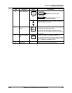
When either of the remote switches
is set for SP2, or when NumSPs = TWO
L = Setpoint 1 (SP) active
R = Setpoint 2 (S2) active
Otherwise, neither indicator
is used.
Indicates temperature
units of PV on display.
MAN
AUTO
SET
UP
FUNC
DISP
Figure 4-7 Operator Interface