


DR4300 Circular Chart Recorder
154 DR4300 Circular Chart Recorder Product Manual 12/03
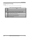
Procedure
The procedure for calibrating the current proportional output is listed in Table 5-11. Make sure “LOCK” in
the Set Up group is set to “NONE.”
For display recorders with 2 pens, be sure the correct input is on display—INP 1 or INP 2 indicator is lit.
Press
FUNC key to change input on display to agree with the control loop output to be calibrated.
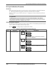
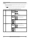
Table 5-11 Procedure for Calibrating Current Output
Step Description Press Action/Result
1
Enter Calibration Mode
SET
UP
until you see
CAL
U
pp
er Dis
p
la
y
CURENT
Lower Display
If “CAL” doesn’t appear or prompt access is denied, check
the “LOCK” configuration.
2
Calibrate 0 %
FUNC
You will see:
U
pp
er Dis
p
la
y
a value (approximately 365)
ZERO
Lower Dis
p
la
y
or
Until the desired 0 % output is read on the milliammeter.
Use the values shown below depending on the action of
your recorder.
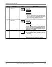
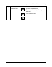
3
Calibrate 100 %
FUNC
Stores the 0 % value and, you will see:
U
pp
er Dis
p
la
y
a value (approximately 1800)
SPAN
Lower Dis
p
la
y
or
Until the desired 100 % output is read on the milliammeter.
Use the values shown below depending on the action of
your recorder.