


DR4300 Circular Chart Recorder
146 DR4300 Circular Chart Recorder Product Manual 12/03
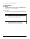
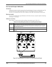
5.4 Input Calibration Set Up and Wiring
5.4.1 General Calibration Set Up
DIP switch settings
Before starting the calibration activity, check that the input switches SW6 on the applicable printed circuit
assembly (pen 1 or pen 2) are set correctly for the type of sensor being calibrated. (See Section 4 –
Configuration, Startup, and Operation of Recorder With Display.)
General set up procedure
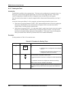
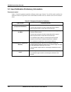
Table 5-4 lists the general set up procedure for all methods of calibration. Do this procedure and then refer
to the set up procedure and diagram specific to your input type.
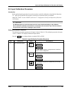
Table 5-4 General Calibration Set Up Procedure
Step Action
1
Set up and connect the calibrator to the input terminals for the applicable printed circuit
assembly in your recorder according to the type of input sensor being used. Refer to the
following figures for corresponding set-up diagrams:
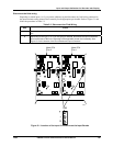
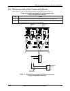
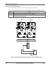
• Figure 5-2 Calibration Set Up Diagram for Thermocouple Inputs
Using a Compensated Calibrator
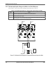
• Figure 5-3 Calibration Set Up Diagram for Thermocouple Inputs Using an Ice Bath
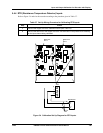
• Figure 5-4 Calibration Set Up Diagram for RTD Inputs
• Figure 5-5 Calibration Set Up Diagram for Millivolts, Volts, and Milliamps Inputs.
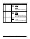
2
Route leads (for example: copper leads or thermocouple extension wires) through a conduit
hole in the recorder case so that you will be able to close the chart plate.
3
Close the chart plate after you have completed the applicable calibration set up.