


DR4300 Circular Chart Recorder
130 DR4300 Circular Chart Recorder Product Manual 12/03
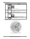
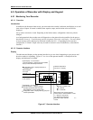
4.5.1.3 Viewing the operating parameters
Contents of display
The upper display uses four characters to display the value of the input. During normal operation, you can
view various real time values and setpoints in the lower six-character display if the recorder supports
control. Each value will be labeled. Press the DISP
key to scroll through the displayed values listed in
Table 4-27. If the recorder does not support control, then only the label “INP” or the totalizer value will
appear in the lower display. (The input value will be in the upper display.)
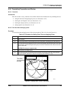
The display shows only those parameters and values that apply to your specific model and the way in
which it was configured. For recorders with two pens, remember that any controller-related values
displayed correspond with the lighted INP indicator. “1” means that the values apply to the pen 1 input
channel and “2” means that the values apply to the pen 2 input channel. Press FUNC
key to toggle
between input 1 and input 2.
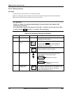
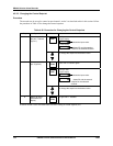
Table 4-27 Lower Display Operating Parameter Labels
Label Description
INP
Process variable value of currently selected input; if the recorder does not support
options, then this label is always displayed. In this case the other parameters listed
below are not applicable.
OT *
Controller output in percent for selected channel’s control loop
SP *
Setpoint for selected channel
S2 *
Second setpoint for selected channel; this setpoint is used only if control group
NumSPs = TWO, or if recorder supports digital inputs, and is configured to use this
alternate setpoint in case an external event triggers the “remote switch”.
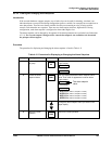
UseSPn *
If a second setpoint is available (because control set up group NumSPs = TWO), use
this to select Setpoint 1 or Setpoint 2.
DE
Process variable deviation from setpoint currently being used.
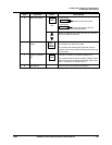
[nnnnnn]
If totalizer is being used, the totalized value will be in the lower display (no label). To
see the scale factor applicable to this value, see the totalizer set up group.
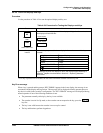
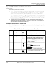
*
If the optional timer is active, either the time remaining on the timer (Hrs:Min), or
*
elapsed time (Hrs:Min) will be displayed. If the “clock hand” is not moving, the timer is
not running.
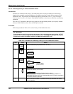
SPRG n *
Select which setpoint program to run; n = 1 to 4.
RUN or
HOLD *
If the optional Setpoint Program feature is currently executing a program, the status
“RUN” or “HOLD” will also be displayed as part of the display cycle.
See
Appendix C for detailed instructions for executing a Setpoint Program.
N nn.nn
Currently executing setpoint program segment (N) and time remaining for segment
(nn.nn) in hours and minutes.
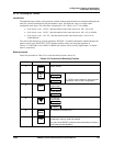
REC nn
Setpoint program cycles remaining. Displayed only if the program was set to run
more than one cycle, and if the program is not executing the last of multiple cycles.
TuneON or
TuneOF *
Status of Accutune II. Displayed only if Accutune is enabled. See Appendix D for
detailed Accutune instructions.
*You can press ▲ or ▼ or to change the value or initiate some action when this parameter is displayed.