


DR4300 Circular Chart Recorder
176 DR4300 Circular Chart Recorder Product Manual 12/03
8.3.3 Background Tests
Tests run automatically
During normal operation of the recorder, tests of the configuration and calibration run in the background. If
the recorder fails one of the tests, the appropriate message will be displayed as described in Subsection
8.3.4.
8.3.4 Error Messages
All relevant messages are displayed
If the recorder fails one or more tests, the operator is alerted by the display of one or more messages.
∗
One
message is displayed at a time on the lower line of the display.
If the problem is with the pen channel input or printed circuit assembly for which real time values are
currently on display, the appropriate error message for each failed test will be displayed. The display will
continue to cycle through the messages until the test is passed.
If the failure is for the pen channel not on display, then a message will alert the operator to the existence of
one or more error messages for the other pen. The message is “Pn ERR”, where n is the number of the pen
with errors not on display. Once the operator has toggled the display to the pen channel whose input or
printed circuit assembly was the source of the error, the display will cycle through the appropriate error
messages.
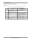
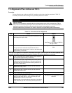
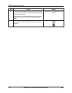
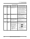
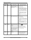
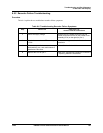
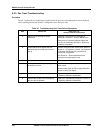
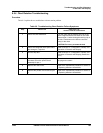
Error messages are listed in Table 8-4, along with the type of test to which each applies, the reason for the
failure, and how to correct the problem.
ATTENTION
In addition to error messages, the recorder will display special status messages when optional features
are active.
• If the lower display flashes “TUNING”, the recorder is in the process of automatically determining
tuning parameters using the Accutune II feature described in Appendix D.
• If the lower display flashes “RUN n” or “HOLD”, the recorder is executing setpoint program “n” as
described in Appendix C, and the run or hold action was initiated locally.
• If the lower display flashes “run n” or “hold”, the recorder is executing setpoint program “n”, and
the run or hold action was initiated remotely.
If you are familiar with the operation of the recorder models without display, you are aware that in those models the
red LED on the printed circuit assembly lights when the unit fails a self-diagnostic, or detects an out-of-range input.
The red LED has a different function in the models with display and keypad. It is not an indication of a
problem. In the models with display the red LED indicates that the display is currently interfacing with this PCA.
Rely on the error messages to notify you of a problem with a recorder with a display. (The flashing green LED is an
indication that the processor is active.)