


Input and Output Calibration for Recorder with Display
12/03 DR4300 Circular Chart Recorder Product Manual 145
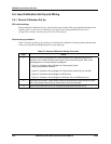
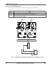
Disconnect the field wiring
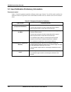
Depending on which input (1 or 2) you plan to calibrate, tag and disconnect any field wiring connected to
the input terminals on the printed circuit assembly for the appropriate pen channel. Refer to Figure 5-1 and
follow the procedure in Table 5-3.
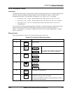
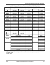
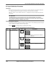
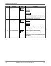
Table 5-3 Disconnect the Field Wiring
Step Action
1
Remove the power from the recorder, open the door on the recorder, and swing the chart plate
out.
2
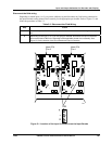
Depending on the input (1 or 2) you are going to calibrate, disconnect the input connections
from terminal block TB2 on the right edge of the applicable printed circuit assembly. See
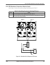
Figure 5-1 for the location of the circuit boards and input connectors.
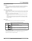
24091
Main PCA
Pen 2
Main PCA
Pen 1
7
TB2
TB1
7
TB2
TB1
TB2
+
R
–
Figure 5-1 Location of the Input Connections on the Input Boards