


DR4300 Circular Chart Recorder
72 DR4300 Circular Chart Recorder Product Manual 12/03
4.2 Operator Interface on Recorder with Display and Keypad
Introduction
The DR4311, DR4312, DR4331 and DR4332 models include a display and keypad used to view real time
values, change setpoints (if the recorder hardware supports outputs), and assign application-specific values
to configuration parameters.
This subsection describes the operator interface, using the display and keypad to configure the recorder,
and procedures for starting up and operating the recorder.
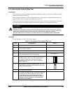
Displays and indicators
The indicators and text displayed let you see what is happening to your process and how the recorder is
responding.
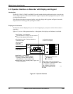
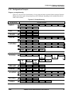
Figure 4-1 is a view of the operator interface. A description of the displays and indicators is included.
24278
INP
OUT
Lower Display - six characters
Normal operation - Displays selected
operating parameter label and value.
With totalization, shows totalizer value.
Configuration mode - Displays Set Up group and
function parameters.
Output relay 1 or 2
is ON, when lit.
Data displayed
is for input
Channel 1 or 2
Upper Display - four characters
Normal operation - Displays process variable
(PV) for the selected input channel.
Configuration mode - Displays selection or
parameter value.
Indicates controller mode:
M = Manual
A = Automatic
1
2
1
2
F
C
R
L
M
A
When either of the remote switches
is set for SP2, or when NumSPs = TWO
L = Setpoint 1 (SP) active
R = Setpoint 2 (S2) active
Otherwise, neither indicator
is used.
Indicates temperature
units of PV on display.
MAN
AUTO
SET
UP
FUNC
DISP
Figure 4-1 Operator Interface