


DR4300 Circular Chart Recorder
80 DR4300 Circular Chart Recorder Product Manual 12/03
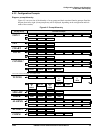
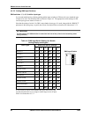
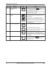
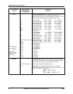
4.3.5.2 Setting SW6 Input Switches
SW6 switches 1, 3, 4, 5, 6 define input type
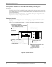
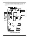
In a recorder model having a display and keypad the input switches at SW6 must be set to match the type
of input to be used. The location of SW6 is shown in Figure 4-3. The appropriate switch settings for the
various input types are shown in Table 4-3.
Note that the setting of switch 2 in SW6 is not related to input type. It is used, along with the “BRNOUT”
parameter in the input group, to specify the effects of an input failure as described in Subsection 4.3.5.3.
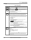
ATTENTION
The ON position for SW6 switches is toward the left side of the printed circuit assembly (when
facing recorder.)
Table 4-3 SW6 Input Switch Settings for Models
Having Display and Keypad
Input Type SW6 Input Switch Settings
1 2 3 4 5 6
0 V to 1 V off
off
ON
off off
0 V to 2 V off
off
ON
off off
0 V to 5 V off
off
ON
off off
0 V to 10 V off
off
ON
off off
2 V to 10 V off
off
ON
off off
1 V to 5 V off
off
ON
off off
0 mV to 10 mV off
off off
ON
off
0 mV to 100 mV off
off off
ON
off
0 to 200 mV
ON
off off off off
0 mA to 20 mA off
off
ON
off
ON
4 mA to 20 mA off
off
ON
off
ON
all thermocouples off
off off
ON
off
all RTDs off off
ON
off
ON
off
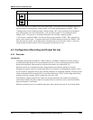
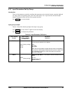
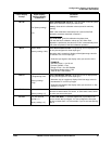
SW6 Input Switch
6
5
4
3
2
1
ON
This switch is used to select whether the input value used by the
recorder should be driven over range or under range in case of input
failure. See Subsection 4.3.5.3.