


Configuration, Startup, and Operation
of Recorder with Display
12/03 DR4300 Circular Chart Recorder Product Manual 139
4.5.2.8 Resetting the Limit Controller
Introduction
The DR4300 is available as a limit controller. On each pen channel’s printed circuit assembly Relay 1 is
used for limit control. When the recorder detects that the input has exceeded the limit (or fallen below the
limit, depending on how the unit is configured) the controller goes to the limit state: Relay 1 is
de-energized.
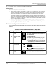
Limit controller operator interface
The operator interface on a limit controller is the same as that of other models having a display and keypad.
The MAN/AUTO/RESET key functions as a reset only. Manual and Auto mode do not apply to the limit
controller.
When the recorder’s controller goes to the limit state (relay de-energized), the operator will be alerted to
the limit state by a message on the bottom line of the display.
• If the input that triggered the limit state is on the pen channel being displayed, the message will be
“LIMIT”.
• If the input that triggered the limit state is on the other pen channel, the message will be “Pn ERR”
(where n is the limit state’s pen channel). Pressing the “FUNC” key to switch channels will display
the “LIMIT” message.
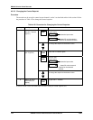
Reset procedure
Follow the procedure in Table 4-35 to reset the limit controller (take it out of the limit state).
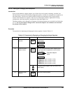
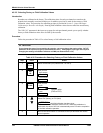
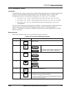
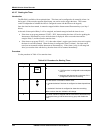
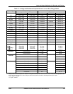
Table 4-35 Procedure for Resetting Limit Controller
Step Press Action
1
Correct the cause of the limit state.
2
FUNC
Select the desired input (indicator INP 1 or INP 2).
3
MAN
AUTO
RESET
Press the RESET key.* The limit controller will resume normal operation,
monitoring the value of the input and comparing it to the configured limit value.
* This refers to the MAN/AUTO/RESET key on the keypad, NOT the reset switch SW2 on the printed
circuit assembly for the pen channel.
The Limit Controller may also be reset remotely; see XRSET function in Subsection 4.3.22.
Output LED is on when relay is energized (not in limit).