


Configuration, Startup, and Operation
of Recorder with Display
12/03 DR4300 Circular Chart Recorder Product Manual 135
4.5.2.4 Viewing and Changing Alarm Setpoints
Introduction
If the recorder hardware supports outputs, one or both relays can be used for alarming. An alarm is an
indication that an event specified during configuration (process variable, for example) has exceeded one or
more alarm limits. There are two alarms available for each pen (assuming no relay is being used for
control). Each alarm has two setpoints. There are two alarm output selections, high and low. During
configuration, each alarm setpoint is configured to alarm either high or low.
The alarm setpoints can be changed by the operator if the alarm parameters are not locked (see Subsection
4.3.19). If a recorder output is being used for control, that output is not available as an alarm and
the prompts will not appear.
Procedure
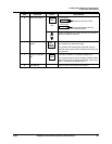
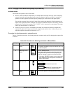
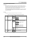
The procedure for displaying and changing the alarm setpoints is listed in Table 4-31.
Table 4-31 Procedure for Displaying or Changing the Alarm Setpoints
Step Operation Press Action/Result
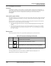
1
Access the Alarm Set
Up group
SET
UP
Until you see:
ALARMS
Lower Display
SET
Upper Displa
y
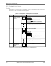
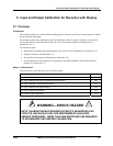
2
Access the Alarm
Setpoint Values
FUNC
Until you display the desired alarm setpoint and its
value. Their order of appearance is shown below.
Lower Display
Upper Displa
y
The alarm setpoint
value
A1S1 VA = (Alarm 1, Setpoint 1 value)
A1S2 VA = (Alarm 1, Setpoint 2 value)
A2S1 VA = (Alarm 2, Setpoint 1 value)
A2S2 VA = (Alarm 2, Setpoint 2 value)
or
Change any alarm setpoint value you select in the
upper display.
3
Return to normal
operation
DISP
Returns to normal operation.