


Installation
12/03 DR4300 Circular Chart Recorder Product Manual
27
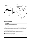
2.5 Input Wiring
Introduction
This section describes procedures for wiring power, analog inputs, optional digital inputs, and the optional
communication link.
2.5.1 Power Wiring
Introduction
Recorder models are available for use with 100 to 240 Vac or 20 Vdc to 27 Vdc power. (See Model
Number in Section 1 Overview.)
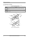
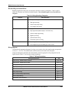
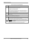
Procedure
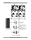
The procedure to connect power wiring is in Table 2-8.
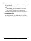
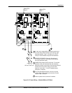
• See
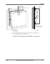
• Figure 2-9 for models without CE Mark.
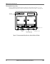
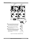
• See
• Figure 2-10 for models with CE Mark.
WARNING
SHOCK HAZARD
Be sure that the line voltage is OFF before connecting the power wires to the recorder.
Failure to observe this precaution can result in serious personal injury or death.
CAUTION
!
This equipment is suitable for connection to 100 to 240 Vac (49 to 61 Hz) or 20 to 27 Vac/Vdc power
supply mains. It is the user’s responsibility to provide a switch and non-time delay (North America),
quick-acting, high breaking capacity, Type F, (Europe) 1/2 A, 250 V fuse(s) or circuit-breaker as part
of the installation. The switch or circuit-breaker shall be located in close proximity to the recorder,
within easy reach of the operator. The switch or circuit-breaker shall be marked as the
disconnecting device for the recorder.