


Input and Output Calibration for Recorder with Display
12/03 DR4300 Circular Chart Recorder Product Manual 141
5. Input and Output Calibration for Recorder with Display
5.1 Overview
Introduction
This section explains how to field calibrate analog inputs, as well as a 4 to 20 mA current output for a model
having a display and keypad.
Because the recorder stores both factory and field calibration values for inputs in memory, you can easily
select either factory or field calibration values for use by the recorder using the procedure given in
Subsection 4.5.2.5.
To calibrate an input:
• Determine the minimum and maximum range values to be used for calibration (see Subsection 5.2).
• Prepare to calibrate (see Subsection 5.3).
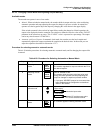
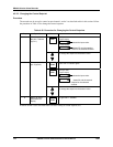
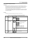
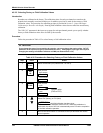
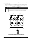
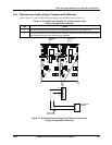
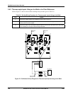
• Set up and wire the input for calibration (see Subsection 5.4).
• Use the parameters in the calibration set up group to store field calibration values in the recorder’s
memory (see Subsection 5.5).
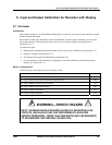
What’s in this section?
The following is a list of the topics covered in this section.
Topic See Page
5.1 Overview 141
5.2 Input Calibration Minimum and Maximum Range Values 142
5.3 Input Calibration Preliminary Information 144
5.4 Input Calibration Set Up and Wiring 146
5.5 Input Calibration Procedure 151
5.6 Current Output Calibration 153
WARNING—SHOCK HAZARD
!
INPUT CALIBRATION MAY REQUIRE ACCESS TO HAZARDOUS LIVE
CIRCUITS, AND SHOULD ONLY BE PERFORMED BY QUALIFIED
SERVICE PERSONNEL. MORE THAN ONE SWITCH MAY BE REQUIRED
TO DE-ENERGIZE UNIT BEFORE CALIBRATION.