


Configuration, Startup, and Operation
of Recorder with Display
12/03 DR4300 Circular Chart Recorder Product Manual 109
4.3.16 Auxiliary Output Set Up Group
Introduction
The auxiliary output set up group lets you enable or disable the auxiliary output selection which provides a
milliampere output representing one of four control parameters: Input, Output, Setpoint, or Deviation. You
can also set the auxiliary output low and high scaling factors.
Auxiliary output group prompts
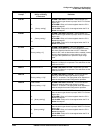
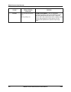
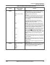
Table 4-14 lists all the function prompts in the auxiliary output set up group and their definitions.
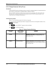
For a 2-pen recorder, the desired input channel is displayed on the left side of the operator interface.
Press FUNC
to select channel.
Press SETUP
key until “AUX OUT” appears in the lower display.
Press FUNC
key to select the parameters.
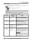
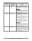
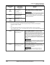
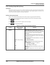
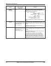
Table 4-14 Auxiliary Output Parameter Definitions
Lower Display
Prompt
Upper Display
Range of Setting
or Selection
Parameter
Definition
AUXOUT
NONE
[factory setting]
INP
OUT
SP
AUXILIARY OUTPUT SELECTION provides an mA
output representing any of four control parameters. The
display for Auxiliary Output viewing will be in engineering
units for all but output. Output will be designated in
percent (%).
The Auxiliary Output is the same output as the Current
Output and is
not available if the control output algorithm
= CUR, CurT, or Tcur.
Other prompts affected by these selections: “4 mA VAL”
and “20mA VAL”.
NO AUXILIARY OUTPUT
INPUT
—This represents the configured range of input.
FOR EXAMPLE:
Type “J” Thermocouple (0 °F to 1600 °F)
0 °F display = 0 % output
1600 °F display = 100 % output
OUTPUT—Represents the displayed controller output in
percent (%).
SETPOINT—Represents the value of the setpoint in units
of PV.