


DR4300 Circular Chart Recorder
DR4300 Circular Chart Recorder Product Manual 12/03
28
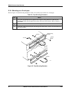
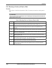
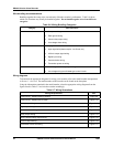
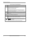
Table 2-8 Procedure for Power Wiring Models
Step Action
1
Open the recorder door. Loosen the captive screw in the chart plate and swing the plate out.
2
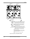
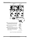
Locate the power terminal block for your recorder model.
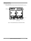
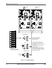
• See Figure 2-9 for models without CE Mark.
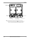
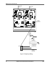
• See Figure 2-10 for models with CE Mark.
Note that the power connection between the boards on two-pen models is made at the
factory. On CE Mark and UL models the connection between the terminal block at the bottom
of the case and the PCA is also made at the factory. In all models, you only have to
connect power to a single terminal block.
3
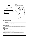
Run the power wires separately through the conduit hole indicated in Figure 2-7 or Figure 2-8.
4
Strip 1/4-inch maximum of insulation from the end of each wire and form end to fit under a
screw connection.
ATTENTION: To avoid damaging the recorder, be sure that you install the power wires into the
correct screw terminals as shown Figure 2-9 and Figure 2-10.
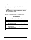
5
Tighten the screws to secure the wires.
6
Dress the wires with as much slack as possible. Do not bundle any low level signal wires with
the power wires. Refer to Table 2-6 for permissible wire bundling.
Refer to Appendix A for additional information concerning noise interference prevention.
WARNING
SHOCK HAZARD
Input line voltage may be present on the instrument ground plane if earth ground is not
attached.
Failure to observe this precaution can result in serious personal injury.