


12/03 DR4300 Circular Chart Recorder Product Manual
xi
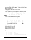
Figures
Figure 1-1 Guide to Manual’s Organization...............................................................................................................10
Figure 2-1 Overall Dimensions ..................................................................................................................................15
Figure 2-2 Plug Locations ..........................................................................................................................................16
Figure 2-3 Mounting Flush in a New Panel Cutout (Rear View)...............................................................................17
Figure 2-4 Panel Mounting Recorder with NEMA4 or Heavy Duty Door ................................................................19
Figure 2-5 Pipe Mounting Brackets............................................................................................................................20
Figure 2-6 Mounting Flush on a Surface of Panel or Wall (Rear View)....................................................................22
Figure 2-7 Recommended Wiring Routing - Models Without CE Mark ...................................................................24
Figure 2-8 Recommended Wiring Routing - Models With CE Mark ........................................................................25
Figure 2-9 Power Wiring – Models Without CE Mark..............................................................................................29
Figure 2-10 Power Wiring – Models With CE Mark .................................................................................................30
Figure 2-11 Analog Input Wiring...............................................................................................................................32
Figure 2-12 Digital Input Wiring ...............................................................................................................................34
Figure 2-13 Communication Wiring ..........................................................................................................................36
Figure 2-14 Relay Output Wiring...............................................................................................................................39
Figure 2-15 Open Collector Output Wiring ...............................................................................................................40
Figure 2-16 Current Output Wiring............................................................................................................................42
Figure 2-17 Transmitter Power Out Wiring ...............................................................................................................44
Figure 3-1 Location of Configuration and Input Switches.........................................................................................47
Figure 3-2 Sample Chart for Single Pen Recorder .....................................................................................................48
Figure 3-3 Basic Chart Plate Components..................................................................................................................66
Figure 3-4 Typical Step Test Chart Patterns...............................................................................................................68
Figure 3-5 Setting Chart Time to Time Index ............................................................................................................69
Figure 4-1 Operator Interface.....................................................................................................................................72
Figure 4-2 Prompt Hierarchy......................................................................................................................................75
Figure 4-3 Location of Switches and Relays..............................................................................................................82
Figure 4-4 Basic Chart Plate Components................................................................................................................120
Figure 4-5 Typical Step Test Chart Patterns.............................................................................................................122
Figure 4-6 Setting Chart Time to Time Index ..........................................................................................................123
Figure 4-7 Operator Interface...................................................................................................................................128
Figure 5-1 Location of the Input Connections on the Input Boards.........................................................................145
Figure 5-2 Calibration Set Up Diagram for Thermocouple Inputs Using a Compensated Calibrator.....................147
Figure 5-3 Calibration Set Up Diagram for Thermocouple Inputs Using an Ice Bath .............................................148
Figure 5-4 Calibration Set Up Diagram for RTD Inputs..........................................................................................149
Figure 5-5 Calibration Set Up Diagram for Millivolts, Volts, and Milliamps Inputs...............................................150
Figure 5-6 Test Equipment Connections for Calibrating Current Output ................................................................153
Figure 6-1 Replacing the Chart and Ink Cartridge ...................................................................................................158
Figure 9-1 Door Assembly .......................................................................................................................................192
Figure 9-2 Chart Plate Assembly..............................................................................................................................193
Figure 9-3 Recorder Components.............................................................................................................................194
Figure 9-4 DR4300 Recorder (CE Mark) – Internal Cabling Diagram....................................................................196
Figure 9-5 DR4300 Recorder (Non-CE Mark) – Internal Cabling Diagram............................................................197
Figure C-1 Ramp/Soak Profile Example..................................................................................................................214