


DR4300 Circular Chart Recorder
124 DR4300 Circular Chart Recorder Product Manual 12/03
4.4.4.3 Diagnostic tests
Tests run automatically
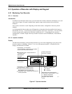
When the recorder is powered-up, self-diagnostics are run by the software.
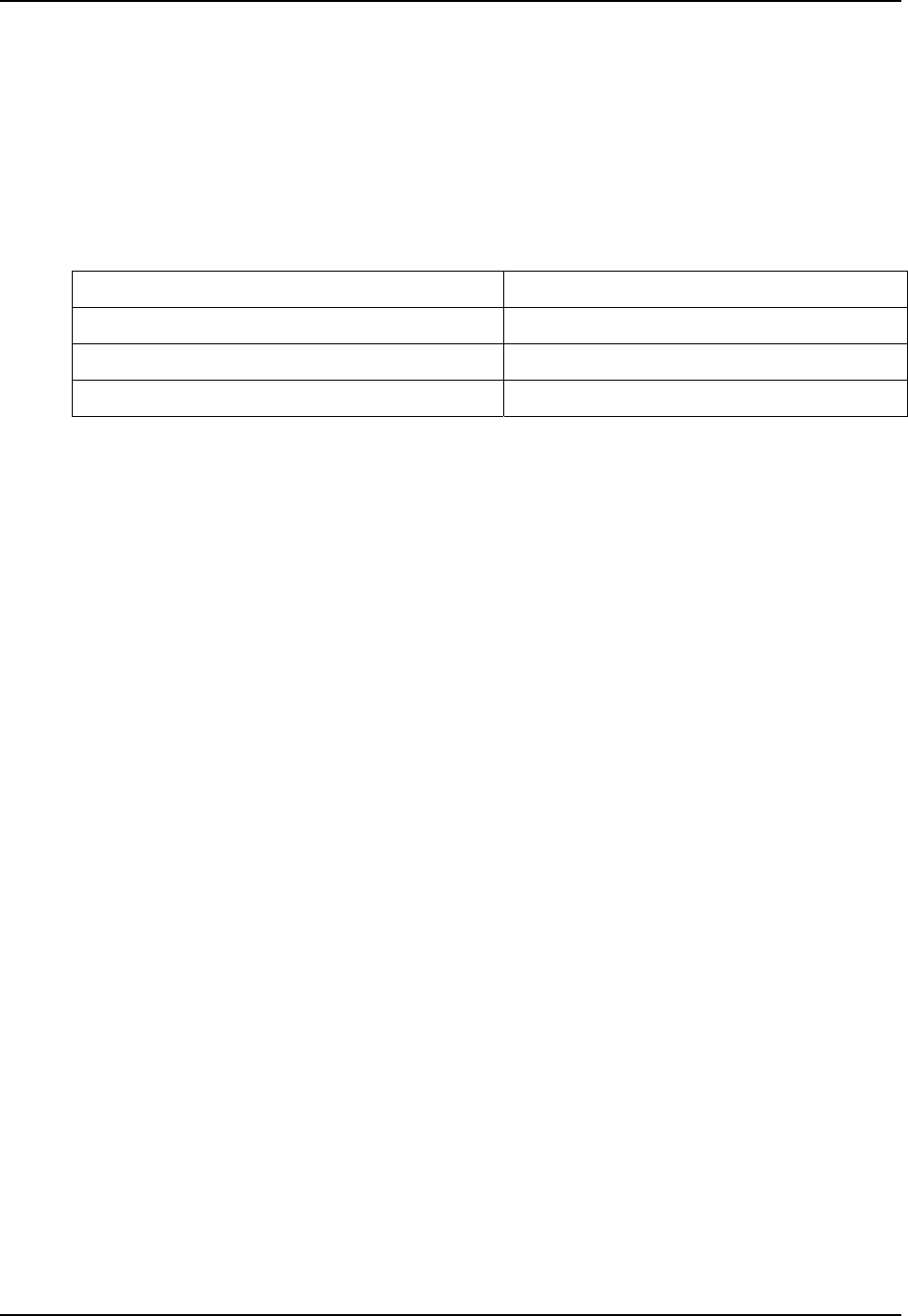
As the tests in Table 4-23 are run, the display indicates whether the tests were passed or failed as described
below.
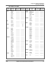
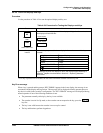
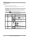
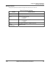
Table 4-23 Power-Up Diagnostic Tests
Lower Display Upper Display
RAMTST
PASS or FAIL
CFGTST (configuration checksum)
PASS or FAIL
CALTST (working calibration)
PASS or FAIL
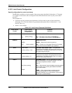
Status of tests displayed
As the tests are run, the lower line of the display shows which test is running. The upper line of the display
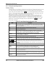
indicates the status. If any of these tests fail, “FAIL” appears momentarily in the upper display, then a
display test is run. The display changes to show the value of the process variable on the top line, and the
error message for the failed test on the second line.
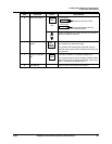
In addition, if the control group parameter “CONTRL” has a value of “ENAB” when the test is failed, the
message “FAILSF” (failsafe) will alternate with error message for the test, and the controller will be in
manual mode. When the “FAILSF” message is displayed, it indicates that the recorder control output has
been driven to the value assigned to the control group “FAILSF” parameter.
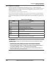
By default, when the recorder is powered up the display will be for pen 1. Therefore, when the power up
tests run, the “PASS” and “FAIL” messages will apply only to the printed circuit assembly associated with
pen 1. However, in a 2-pen recorder the tests will also be run on the printed circuit assembly for pen 2. If
the pen 2 assembly fails one of the tests, the message “P2 ERR” will be displayed, along with any error
messages from the pen 1 tests.
Section 8 contains additional information about self-diagnostics, and suggested remedies if a problem is
detected.