


DR4300 Circular Chart Recorder
152 DR4300 Circular Chart Recorder Product Manual 12/03
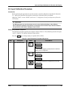
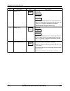
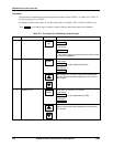
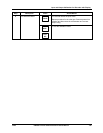
Step Description Press Action/Result
2
Calibrate 0 %
FUNC
You will see:
APLY
U
pp
er Dis
p
la
y
INZERO
Lower Display
• Adjust your calibration device to an output signal equal
to the 0 % range value for your particular input type. See
Table 5-1 for Voltage or Resistance equivalents.
• Wait 60 seconds, then go to the next step.
3
Calibrate 100 %
FUNC
You will see:
APLY
U
pp
er Dis
p
la
y
INSPAN
Lower Dis
p
la
y
Adjust your calibration device to an output signal equal to
the 100 % range value for your particular input type (see
Table 5-1 for voltage or resistance equivalents). Wait 60
seconds, then go to next step.
4
Exit the Calibration Mode
FUNC
The recorder stores the calibration constants.
The value of input set up group parameter “LD CAL” is set
to “FLD” (field).
The recorder begins to use the new field calibration values
for this channel.
Repeat this procedure for the other pen, if required.