


Input and Output Calibration for Recorder with Display
12/03 DR4300 Circular Chart Recorder Product Manual 149
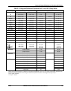
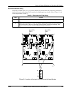
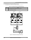
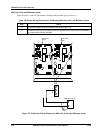
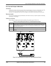
5.4.4 RTD (Resistance Temperature Detector) Inputs
Refer to Figure 5-4 and wire the recorder according to the procedure given in Table 5-7.
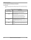
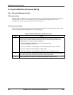
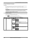
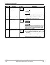
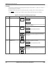
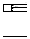
Table 5-7 Set Up Wiring Procedure for Calibrating RTD Inputs
Step Action
1
Connect the copper wire to the calibration source (see Table 5-3).
2
Connect the other end of the copper wire to the TB2 terminals on the printed circuit assembly
for the input channel being calibrated.
Main PCA
Pen 2
Main PCA
Pen 1
7
TB2
TB1
7
TB2
TB1
TB2
+
R
–
-
+
Decade box
Copper
wires
24093
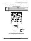
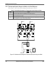
Figure 5-4 Calibration Set Up Diagram for RTD Inputs