


Installation
12/03 DR4300 Circular Chart Recorder Product Manual
43
2.6.3 Transmitter Power Out
Introduction
A recorder model is available that provides +24 Vdc power out to a transmitter.
Procedure
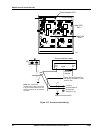
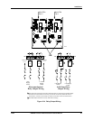
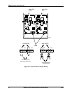
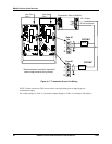
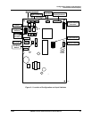
Refer to Figure 2-17 and follow the procedure in Table 2-15 to wire the transmitter power out.
Table 2-15 Transmitter Power Out Wiring
Step Action
ATTENTION To avoid damaging the recorder, be sure that you install the power wires into the
correct screw terminals as shown in Figure 2-9 and Figure 2-10.
1
Turn off the power to the recorder.
2
Open the recorder door. Loosen the captive screw in the chart plate and swing the plate out.
3
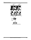
Locate the DC OUT terminal block on the Transmitter Power Module, located above the
printed circuit assembly (PCA) for pen 1. (See Figure 2-17.)
4
Run the output wires through the appropriate conduit hole (see Figure 2-7 and Figure 2-8).
Refer to Table 2-6 for acceptable wire bundling.
5
Strip 1/4-inch maximum of insulation from the end of each wire and form end to fit under a
screw connection.
6
Insert the wires under the appropriate screws for the transmitter power out as shown in the
figure. Tighten the screws to secure the wires.