


Configuration, Startup, and Operation
of Recorder without Display
12/03 DR4300 Circular Chart Recorder Product Manual 45
3. Configuration, Startup, and Operation of
Basic Recorder without Display
3.1 Overview
Introduction
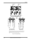
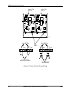
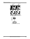
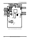
Set up the functionality of the models that do not have a display and keypad using configuration and input
switches. Each pen channel in the recorder has an associated printed circuit assembly (PCA) shown in
Figure 3-1. The configuration switches are the SW1 switchbank. The input switches are the SW6
switchbank. If your recorder is equipped with two pens, the printed circuit assemblies for the two pens can
be set up differently. The PCA for pen 1 (purple) is on the right (when facing the recorder); the PCA for
pen 2 (red) is on the left (if present).
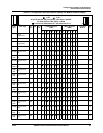
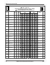
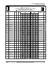
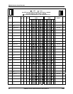
Set up is fast and easy. This section includes a table that shows the various available combinations of
recording selections (such as chart range, length of time for single rotation of chart, whether the input is
linear or non-linear), input actuation types, and whether jumper R56 should be in or out. Find your desired
configuration for the pen 1 channel on the table, then set the SW1 and SW6 switches as indicated. Repeat
the process for the pen 2 channel, if available on your recorder, and set up is complete.
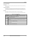
What’s in this section?
The following is a list of topics covered in this section.
Topic See Page
3.1 Overview 45
3.2 Configuration (Recording Set Up) 46
3.3 Startup and Operation 65
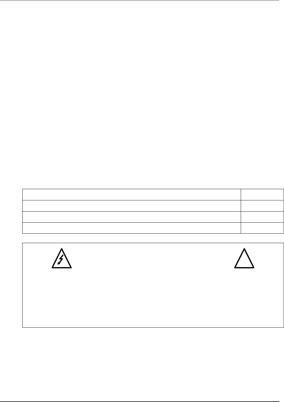
WARNING—SHOCK HAZARD
!
SET THE SWITCHES DESCRIBED IN THIS SECTION WITH THE UNIT
POWER DISCONNECTED. DO NOT TOUCH POWER CONNECTIONS
AT TB1. FAILURE TO OBSERVE THIS PRECAUTION CAN RESULT IN
EXPOSURE TO A POTENTIALLY LETHAL SHOCK HAZARD. MORE THAN
ONE SWITCH MAY BE REQUIRED TO DE-ENERGIZE UNIT.