


Configuration, Startup, and Operation
of Recorder with Display
12/03 DR4300 Circular Chart Recorder Product Manual 89
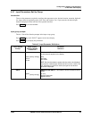
4.3.8 Pen Parameters Set Up Group
Introduction
The functions in this group are used to configure the pen(s). The procedure for configuring each pen is the
same. For a 2-pen recorder, the desired input channel is displayed on the left side of the operator interface.
Press FUNC
key to select channel.
Pen group prompts
Table 4-6 lists all the function prompts in the pen set up group.
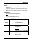
Press the SET UP
key until “PEN” appears in the lower display.
Press FUNC
key to display parameters.
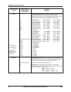
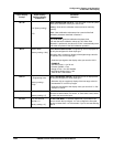
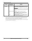
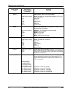
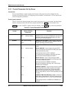
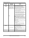
Table 4-6 Pen Parameter Definitions
Lower Display
Prompt
Upper Display
Range of Setting
or Selection
Parameter
Definition
PEN IN
INP
[factory setting]
REM1
REM2
OUT*
SP*
PEN INPUT—What do you want the pen to record?
INPUT—Records the input for given channel.
REMOTE SWITCH 1 EVENT—Records the digital input
event for given channel. (Event toggles pen between
90 % and 95 % on chart.)
REMOTE SWITCH 2 EVENT—Records the digital input
event for given channel. (Event toggles pen between
80 % and 85 % on chart.)
OUTPUT
—Records the output for the channel.
SETPOINT
—Records setpoint for given channel.
*Only selectable if hardware supports outputs and
function prompt “CONTRL” in Control group is set to
“ENAB” (enabled).
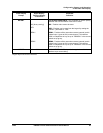
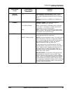
CHT HI
–999 to 9999
[factory setting = 780]
CHART HIGH RANGE VALUE—Enter a value that
corresponds with the chart high range value for
the pen. (This is the value that prints at the outer edge of
the chart. If you had a range of 0 °C to –400 °C, –400
would be the chart high range value.)
CHT LO
–999 to 9999
[factory setting = 730]
CHART RANGE LOW VALUE—Enter a value that
corresponds with the chart low range value for the
pen.