


Installation
12/03 DR4300 Circular Chart Recorder Product Manual
33
2.5.3 Digital Inputs (Optional)
Introduction
If the recorder hardware supports optional digital inputs, the inputs are wired to the terminal block on the
digital input board mounted on stand-offs on the printed circuit assembly for the pen channel.
Procedure
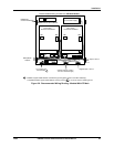
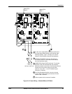
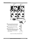
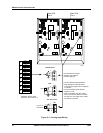
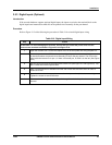
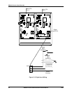
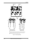
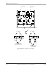
Refer to Figure 2-12 while following the procedure in Table 2-10 to install digital input wiring.
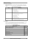
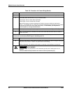
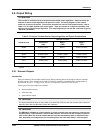
Table 2-10 Digital Input Wiring
Step Action
ATTENTION To avoid damaging the recorder, be sure that you install the power wires into the
correct screw terminals as shown in Figure 2-9 and Figure 2-10.
1
Open the recorder door. Loosen the captive screw in the chart plate and swing the plate out.
2
Locate the terminal block, P3D, on the optional digital input printed circuit assembly mounted
on stand-offs above the printed circuit assembly (PCA) for the pen channel. The PCA on the
right inside the recorder is for pen 1; if there is a second pen, its PCA is on the left. (See Figure
2-12.)
3
Run the input wires through the appropriate conduit hole (see Figure 2-7 and Figure 2-8). DO
NOT bundle them with the power wires.
4
Strip 1/4-inch maximum of insulation from the end of each wire and form end to fit under a
screw connection.
5
Insert the wires under the appropriate screws for the input number (labeled on assembly).
Tighten the screws to secure the wires.
6
If the recorder has two pens, repeat Steps 2 through 5 to wire the input for the second pen
channel.