


Configuration, Startup, and Operation
of Recorder with Display
12/03 DR4300 Circular Chart Recorder Product Manual 97
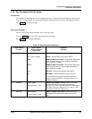
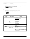
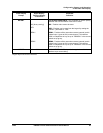
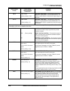
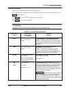
Lower Display
Prompt
Upper Display
Range of Setting
or Selection
Parameter
Definition
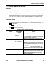
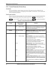
SP HI
–999 to 9999
[factory setting = 100]
SETPOINT HIGH LIMIT*—This selection prevents the
setpoint from going above the value selected here. The
setting must be equal to or less than the upper range of
the input.
SP LO
–999 to 9999
[factory setting = 0]
SETPOINT LOW LIMIT*—This selection prevents the
setpoint from going below the value selected here. The
setting must be equal to or greater than the lower range
of the input.
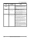
*The setpoint will automatically adjust itself to be within the setpoint limit range. For example, if SP = 1500 and SP HI
is changed to 1200, the new setpoint will be 1200.
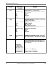
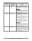
ACTION
CONTROL OUTPUT DIRECTION—In what direction do
you want the recorder output to go when the process
variable increases.
DIR [factory setting]
DIRECT ACTING CONTROL—The recorder's output is
ON or increasing when the difference between setpoint
and PV (PV–SP) is positive.
RE
REVERSE ACTING CONTROL—The recorder's output is
OFF or decreasing when the difference between setpoint
and PV (PV–SP) is negative.
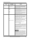
OUT HI
0 % to 100.0 % of output for
relay output
–5 % to 105 % for current
output
[factory setting = 100]
HIGH OUTPUT LIMIT—This parameter is used to specify
the highest output to be used in Auto mode.
This prompt is displayed only if the “CTRALG” (control
algorithm) is set to “PIDA” or “PDMR”.
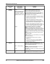
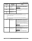
OUT LO
0 % to 100.0 % of output for
relay output
–5 % to 105 % for current
output
[factory setting = 0]
LOW OUTPUT LIMIT—This parameter is used to specify
the lowest output to be used in Auto mode.
This prompt is displayed only if the “CTRALG” (control
algorithm) is set to “PIDA” or “PDMR”.
DBAND
–5.0 % to 25.0 %
[factory setting = 0]
DEADBAND— Use this parameter to specify an
adjustable gap between the operating ranges of relay 1
and relay 2 in which neither relay operates (positive
value) or both relays operate (negative value). It is the
difference between the nominal trip points of relay 1 and
relay 2.
This prompt appears only if control group function prompt
“OUTALG” is set to “RLYD”, “CurT”, or “Tcur”.
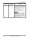
HYST
0.0 % to 5.0 % of PV span
[factory setting = 0]
HYSTERESIS (OUTPUT RELAY ONLY) is an adjustable
overlap of the ON/OFF states of each control relay. This
is the difference between the value of the process
variable at which the control relays energize and the
value at which they de-energize. Only applicable for
ON/OFF control.