


Installation
12/03 DR4300 Circular Chart Recorder Product Manual
37
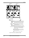
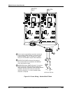
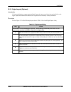
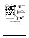
2.6 Output Wiring
ATTENTION
The recorder is available with several options and multiple output algorithms. Output terminal use
depends on which output algorithm and options are used. The wiring diagrams in this section
show how to wire the terminals. To see which terminals are used for what output function, refer to
Table 2-12. This table applies to all control types. Each pen channel is configured separately, and
each can use a different output algorithm. (The output algorithm is set with the control set up group
“OUTALG” parameter.)
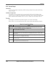
Table 2-12 Output Terminal Use for Output Algorithm and Option Combinations
Terminal Function
OUTALG value Current Out
(TB5)
Relay 1
(TB4)
Relay 2
(TB3)
NONE auxilary output* alarm 1 alarm 2 or timer*
RLY auxilary output* control alarm 2 or timer*
RLYD auxilary output* control 1 (heat) control 2 (cool)
CUR control alarm 1 alarm 2 or timer*
CurT control (cool) control (heat) alarm 2 or timer*
Tcur control (heat) control (cool) alarm 2 or timer*
*Option
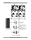
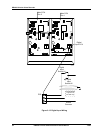
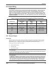
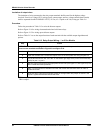
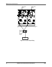
2.6.1 Discrete Outputs
Introduction
Each pen channel in the recorder models having display and keypad can be equipped with two optional
discrete outputs. These outputs can be used for control or alarming, depending on the configuration as
described in Section 4 – Configuration, Startup, and Operation of Recorder with Display.
Three types of discrete outputs are available:
• electromechanical relay
• solid state relay
• open collector output
ATTENTION
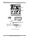
The electromechanical relays on the printed circuit assembly (PCA) for each pen channel can be wired for
Normally Open (NO) and Normally Closed (NC) operation.
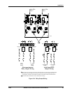
ATTENTION
The DR4300 is available as a limit controller. In a limit controller each pen channel’s printed circuit
assembly Relay 1 (TB4 terminals 3 and 2 for NO contacts, and 2 and 1 for NC contacts) is used for
limit control. When the recorder detects that the input has exceeded the limit (or fallen below the
limit, depending on configuration), the controller goes to the limit state: Relay 1 is de-energized.