


Configuration, Startup, and Operation
of Recorder with Display
12/03 DR4300 Circular Chart Recorder Product Manual 79
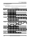
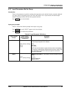
4.3.5 Switch Settings
4.3.5.1 Introduction
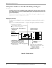
Significance of hardware switches in models with display
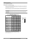
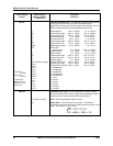
SW6 input switches: The display and keypad are used to configure the software on each pen channel’s
printed circuit assembly (PCA). In addition, the input hardware switches 1, 3, 4, 5 and 6 in SW6 must be
set to match the input type as described in Subsection 4.3.5.2. This is required so that the recorder
hardware will provide an appropriate value to the recorder software.
SW6 burnout switch 2: This burnout switch should be set to specify whether the input used by the
recorder for the channel should be sent over range or under range if the input to the recorder fails while the
“BRNOUT” parameter value is “NONE”. Alternatively, if the “BRNOUT” parameter has a value of “UP”
or “DOWN” switch 2 should be set to match. Details are provided in Subsection 4.3.5.3.
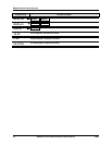
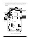
SW1 configuration switches: In a recorder model having a display and keypad all switches in SW1 will
be ignored if the cable from the display and keypad assembly is plugged into J4 on the PCA associated
with the pen channel. (SW1 switches are used to configure recorder models that do not have a display and
keypad as described in Section 3.)
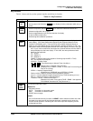
ATTENTION
If the display cable is disconnected after the software has been configured using the display and
keypad, the recorder’s behavior will depend on the settings of the SW1 switches. If all SW1
switches are in the OFF position when the cable is disconnected, the recorder will continue to use
the software configuration entered with the display and keypad. However, if all SW1 switches are
not OFF when the cable is disconnected, the recorder will use the configuration in Table 3-2 that
matches the SW1 switch settings. (If the switch setting combination does not match any
configuration in Table 3-2, the recorder will use configuration #1.)
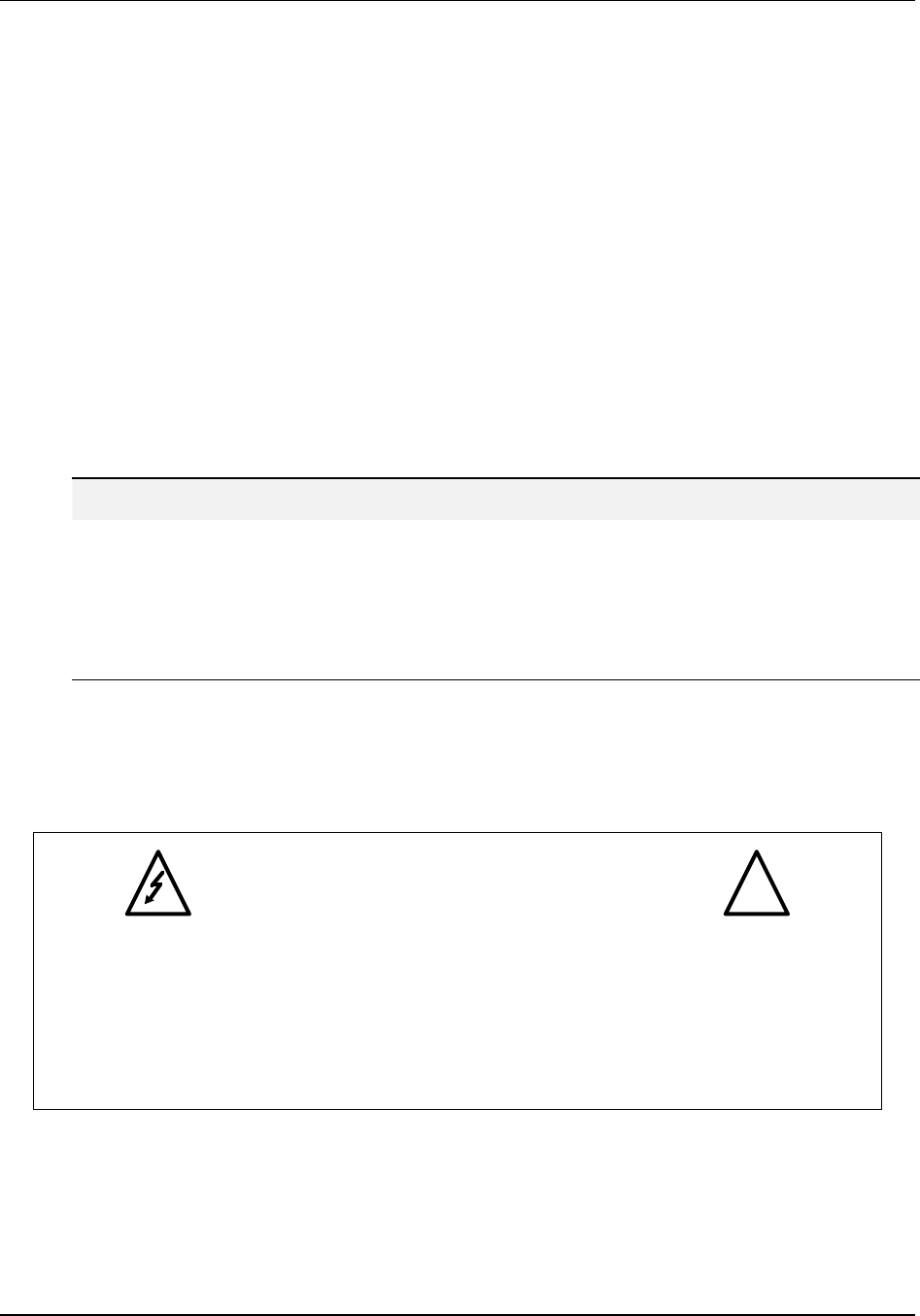
Safety precautions
Exercise appropriate safety precautions when setting switches.
WARNING—SHOCK HAZARD
!
SET THE SWITCHES DESCRIBED IN THIS SECTION WITH THE UNIT
POWER DISCONNECTED. DO NOT TOUCH POWER CONNECTIONS
AT TB1. FAILURE TO OBSERVE THIS PRECAUTION CAN RESULT IN
EXPOSURE TO A POTENTIALLY LETHAL SHOCK HAZARD. MORE THAN
ONE SWITCH MAY BE REQUIRED TO DE-ENERGIZE UNIT.