


DR4300 Circular Chart Recorder
136 DR4300 Circular Chart Recorder Product Manual 12/03
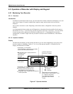
4.5.2.5 Selecting Factory or Field Calibration Values
Introduction
Recorders are calibrated at the factory. The calibration values for each pen channel are stored on the
printed circuit assembly associated with the pen. In addition, provision is made for the storage of field
calibration values. The procedure for calibrating an input is provided in Section 5 – Input and Output
Calibration for Recorder with Display. Entering field calibration values does not affect the stored factory
calibration.
The “LD CAL” parameter in the input set up group for each pen channel permits you to specify whether
factory or field calibration values are to be used by the recorder.
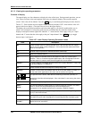
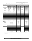
Procedure
Follow the procedure in Table 4-32 to select factory or field calibration values.
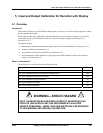
ATTENTION
If you change the type of input used by the recorder, you must change the setting of the “IN TYP”
parameter in the input set up group (see Subsection 4.3.7). Changing the input type also requires
changing the settings of hardware switches at SW6 (see Subsection 4.3.5.2).
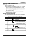
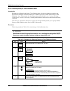
Table 4-32 Procedure for Selecting Factory or Field Calibration Values
Step Press Action
1
FUNC
Select the desired input (indicator INP 1 or INP 2).
2
SET
UP
Until you see:
Lower Display
SET
Upper Displa
y
INPUT
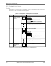
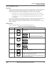
3
FUNC
Until you see:
U
pp
er
Present value
(FAC or FLD)
LD CAL
Lower
4
or
Select FAC (factory) or FLD (field).
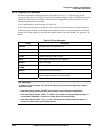
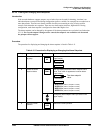
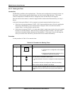
ATTENTION
Until field calibration has been done,
FLD uses the same calibration values as FAC. When field calibration is
performed, the value of LD CAL is automatically set to FLD at the completion
of the field calibration operation.
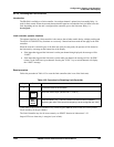
5
Be sure the correct sensor is connected to the input terminals and resume
normal operation.