


Configuration, Startup, and Operation
of Recorder with Display
12/03 DR4300 Circular Chart Recorder Product Manual 121
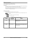
4.4.3 Running the Optional Step Test
Introduction
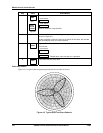
You can test the recorder’s mechanical operation by running a step test. This test is initiated using the
keypad as described in Table 4-21.
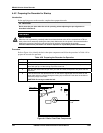
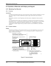
This test prints a step pattern, which is independent of any chart settings, with horizontal lines drawn by
both pens at each 10 % increment on the chart (see Figure 4-5).
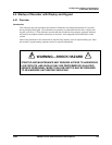
WARNING
SHOCK HAZARD
When the unit is powered a potentially lethal shock hazard exists at the AC line connections at TB1 on
each printed circuit assembly (behing the chart plate). Make sure the unit power is disconnected before
starting the procedure. More than one switch may be required to de-energize the recorder.
Failure to observe this precaution can result in exposure to a potentially lethal shock hazard.
The test will run for one complete revolution of the chart before it stops itself. The chart revolution for the
test takes approximately 2 minutes, regardless of configured chart speed. However, the test can be
terminated at any time by pressing the DISP
key.
Additional automatic self-tests
At power-up the recorder runs self-diagnostics on the printed circuit assembly for each pen. See Section
4.5.1.4 and Section 8 – Troubleshooting and Pen Alignment of Recorder with Display for more information
about these diagnostic tests.
Procedure
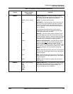
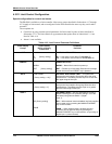
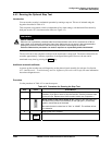
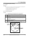
Use the procedure in Table 4-21 to run the step test.
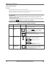
Table 4-21 Procedure for Running the Step Test
Step Press Action/Result
1
Make sure the cap is removed from the tip of each pen and the chart is
installed. (If you plan to store or ship the recorder, save the protective caps
for the pen tips. Replace them if the recorder is taken out of operation.)
2
Being careful of the shock hazard at TB1, swing out the chart plate and
set SW5 on the printed circuit assembly on the right (pen 1) to the setup
position, toward the top of the board.
Be certain that the Lockout level is "CAL" or "NONE". The self-test will not
run otherwise.
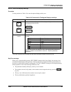
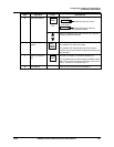
3
Apply power to the recorder.
4
FUNC
Until INP 1 indicator is lit on the left side of the operator interface.